Kawasaki Diesel MULE 4010 TRANS 4x4 (KAF950G9). Manual - part 119
 

  Index      Engines     Kawasaki Diesel MULE 4010 TRANS 4x4 (KAF950G9) - service manual


Search            


Content   ..  117  118  119  120   ..


Kawasaki Diesel MULE 4010 TRANS 4x4 (KAF950G9). Manual - part 119


17-22 ELECTRICAL SYSTEM

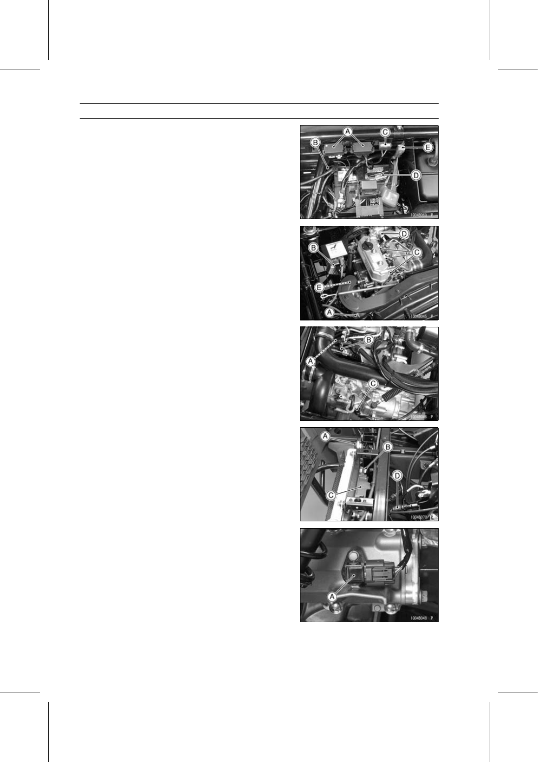
Parts Location

Fuse Box [A]
Frame Ground Terminal [B]
Radiator Fan Breaker [C]
Battery 12 V 52 Ah [D]
50 A Fuse [E]

Starter Motor [A]
Alternator [B]
Glow Plugs [C]
Coolant Temperature Switch [D]
Engine Ground Terminal [E]

Oil Pressure Switch [A]
Fuel Cut Solenoid Valve [B]
Neutral Switch [C]

Horn [A]
Radiator Fan Switch [B]
Radiator Fan [C]
Brake Light Switch [D]

Speed Sensor [A]

ELECTRICAL SYSTEM 17-23

Precautions

There are a number of important precautions that are

musts when servicing electrical systems. Learn and ob-
serve all the rules below.

Do not reverse the battery cable connections. This will
burn out the diodes in the electrical parts.

Always check battery condition before condemning other
parts of an electrical system. A fully charged battery is a
must for conducting accurate electrical system tests.

The electrical parts should never be struck sharply, as
with a hammer, or allowed to fall on a hard surface. Such
a shock to the parts can damage them.

To prevent damage to electrical parts, do not disconnect
the battery cables or any other electrical connections
when the main switch is ON, or while the engine is
running.

Because of the large amount of current, never keep the
main switch turned to the start position when the starter
motor will not turn over, or the current may burn out the
starter motor windings.

Take care not to short the cables that are directly con-
nected to the battery positive (+) terminal to the chassis
ground.

Troubles may involve one or in some cases all items.
Never replace a defective part without determining what
CAUSED the failure. If the failure was brought on by
some other item or items, they too must be repaired or
replaced, or the replacement part will soon fail again.

Make sure all connectors in the circuit are clean and tight,
and examine wires for signs of burning, fraying, etc. Poor
wires and bad connections will affect electrical system op-
eration.

Measure coil and winding resistance when the part is cold
(at room temperature).

17-24 ELECTRICAL SYSTEM

Electrical Wiring

Wiring Inspection

Visually inspect the wiring for signs of burning, fraying,
etc.
If any wiring is poor, replace the damaged wiring.

Pull each connector [A] apart and inspect it for corrosion,
dirt, and damage.
If the connector is corroded or dirty, clean it carefully. If it
is damaged, replace it.

Check the wiring for continuity.

Use the wiring diagram to find the ends of the lead which
is suspected of being a problem.

Connect the hand tester between the ends of the leads.

Special Tool - Hand Tester: 57001-1394

Set the tester to the ×1 Ω range, and read the tester.
If the tester does not read 0 Ω, the lead is defective. Re-
place the lead or the wiring harness if necessary.

ELECTRICAL SYSTEM 17-25

Battery

In this model, two batteries are prepared.

Conventional Type Battery [A] (KAF950G9

∼ GC/HA,

Other Than US Model)
The caps [B] can be removed.

Sealed Type Battery [A] (US Model and KAF950GD)

Battery Removal

Tilt up the front seat.

Remove the front seat lower cover rear (see Floor Center
Panel Removal in the Frame chapter).

Slide the positive terminal cover [A] out.

Disconnect the battery negative (–) cable and lead [B]
first, and then the positive (+) cable and leads [C].

Remove:

Battery Holder Mounting Nuts [D]
Battery Holder [E]

Remove the battery [F] backward [G].

Battery Installation

Check that the rubber dampers [A] on the battery case [B]
and battery holder [C] are properly in place.

Install the battery case [A] so that the long side [B] faces
right side [C].


Content   ..  117  118  119  120   ..