Kawasaki Diesel MULE 4010 TRANS 4x4 (KAF950G9). Manual - part 125
 

  Index      Engines     Kawasaki Diesel MULE 4010 TRANS 4x4 (KAF950G9) - service manual


Search            


Content   ..  123  124  125  126   ..


Kawasaki Diesel MULE 4010 TRANS 4x4 (KAF950G9). Manual - part 125


17-46 ELECTRICAL SYSTEM

Electric Starter System

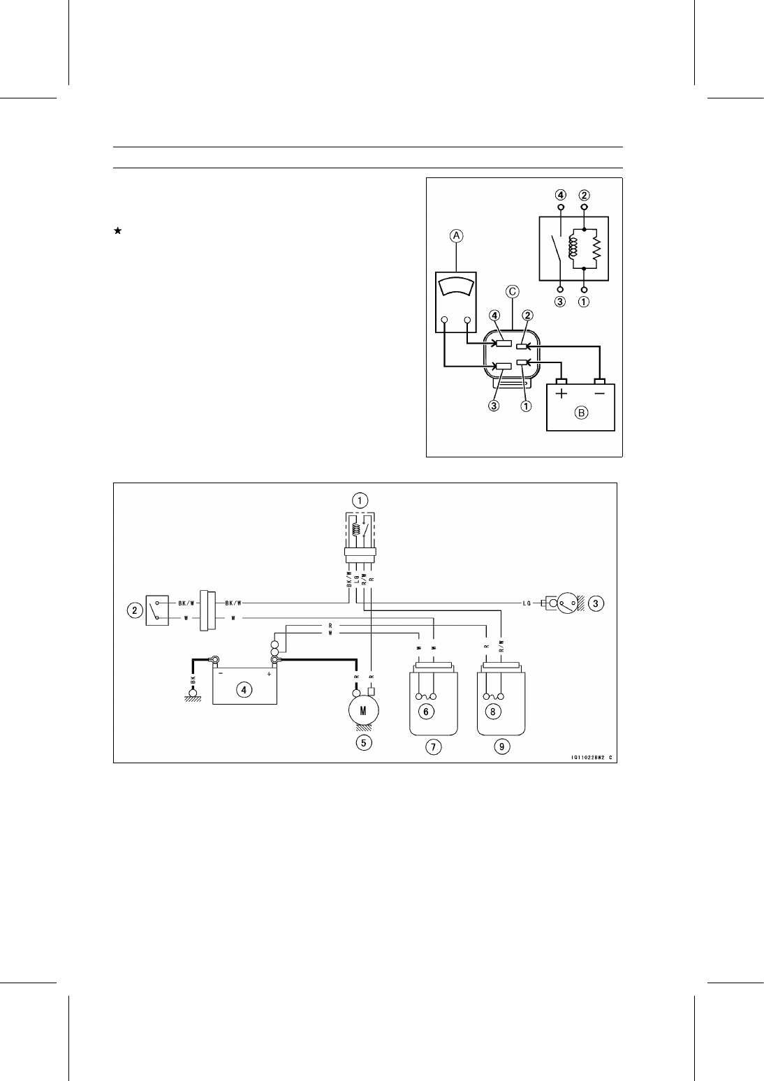
Connect the hand tester [A] and 12 V battery [B] to the
starter circuit relay [C] as shown in the figure.

Special Tool - Hand Tester: 57001-1394

If the relay does not work as specified, the relay is defec-
tive. Replace the relay.

Testing Relay

Hand Tester Range: × 1 Ω
Criteria:

When battery is connected → 0 Ω
When battery is disconnected → ∞ Ω

Relay Coil Terminals [1] and [2]
Relay Switch Terminals [3] and [4]

Electric Starter Circuit

1. Starter Circuit Relay
2. Main Switch
3. Neutral Switch
4. Battery
5. Starter Motor
6. Main Fuse 30 A
7. Fuse Box 2
8. Starter Relay Fuse 30 A
9. Fuse Box 1

ELECTRICAL SYSTEM 17-47

Preheating System

Glow Plug Removal

Tilt up the cargo bed.

Remove the caps [A].

Remove:

Connecting Plate Nuts [A]
Connecting Plate [B]
Glow Plug Lead [C]

Remove the glow plug [A].

Glow Plug Installation

Tighten:

Torque - Glow Plugs: 17 N·m (1.7 kgf·m, 13 ft·lb)

Connecting Plate Nuts: 1.2 N·m (0.12 kgf·m, 11

in·lb)

Glow Plug Inspection

Using the × 1 Ω range of the hand tester, measure the
resistance between the terminal [A] and the housing [B]
of the glow plug.

Special Tool - Hand Tester: 57001-1394

If the tester does not read as specified, replace the glow
plug.

Glow Plug Resistance:

About 0.1

∼ 5.0 Ω

NOTE

Be careful not to apply the battery voltage to the glow
plug directly.

Be careful not to scratch the heater section [C].

17-48 ELECTRICAL SYSTEM

Preheating System

Preheating Timer Inspection

Remove the front seat lower cover left (see Starter Relay
Inspection).

Check that the main switch is turned OFF, and connect
the hand tester [A] to the preheating timer [B] as follows.

Special Tool - Hand Tester: 57001-1394

Hand Tester Range: DC 25 V
Hand Tester (+) Lead → Black Lead Terminal
Hand Tester (–) Lead → Ground

When the main switch is turned ON, the reading should
show less than 1.8 V during 5 seconds.
If the preheating timer does not work, replace the timer.

Glow Plug Relay Inspection

Remove:

Front Seat Lower Cover Left (see Starter Relay Inspec-
tion)
Mounting Bolt [A] and Nut
Glow Plug Relay [B]
Glow Plug Relay Lead Connectors [C]

Connect the hand tester [A] and 12 V battery [B] to the
glow plug relay [C] as shown in the figure.

Special Tool - Hand Tester: 57001-1394

If the relay does not work as specified, the relay is defec-
tive. Replace the relay.

Testing Relay

Hand Tester Range: × 1 Ω
Criteria:

When battery is connected → 0 Ω
When battery is disconnected → ∞ Ω

Relay Coil Terminals [85] and [86]
Relay Switch Terminals [30] and [87]

Glow Plug Relay Installation

Connect the leads to the glow plug relay terminals as fol-
lows.

Black Lead (Tag No. 85)

to Terminal No. 85 [A]

Brown Lead (Tag No. 86)

to Terminal No. 86 [B]

Black/White Lead (Tag
No. 87)

to Terminal No. 87 [C]

Black/White Lead (Tag
No. 30)

to Terminal No. 30 [D]

ELECTRICAL SYSTEM 17-49

Preheating System

Preheating System Circuit

1. Neutral Switch
2. Starter Circuit Relay
3. Glow Plug Relay
4. Glow Plug Light
5. Main Switch
6. Glow Plugs
7. Battery
8. Main Fuse 30 A
9. Preheating Timer Fuse 5 A

10. Fuse Box 2

11. Starter Relay Fuse 30 A

12. Fuse Box 1
13. Preheating Timer


Content   ..  123  124  125  126   ..