Kawasaki Diesel MULE 4010 TRANS 4x4 (KAF950G9). Manual - part 127
 

  Index      Engines     Kawasaki Diesel MULE 4010 TRANS 4x4 (KAF950G9) - service manual


Search            


Content   ..  125  126  127  128   ..


Kawasaki Diesel MULE 4010 TRANS 4x4 (KAF950G9). Manual - part 127


17-54 ELECTRICAL SYSTEM

Meter, Gauge

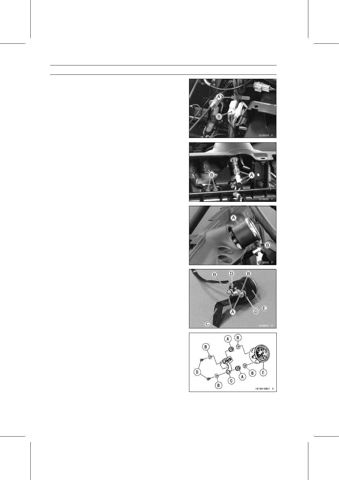
Speedometer Removal

Remove:

Front cargo compartment (see Front Cargo Compart-
ment Removal in the Frame chapter).
Band [A]

Disconnect the speedometer illumination lead connector
[B].

Remove:

Speedometer Cable [A]
Meter Bracket Bolts [B] and washers

Remove the speedometer [A] backward [B].

Remove:

Speedometer screws [A] and washers [B]
Speedometer bracket [C] and washers [D]
Speedometer [E]
Remove the rubber dampers as necessary.

Remove the rubber dampers as necessary.

Speedometer Installation

Install the following parts as shown in the figure.

Rubber Dampers [A]
Washers [B]
Speedometer Bracket [C]
Speedometer Screws [D]
Speedometer [E]

Install the two rubber dampers of the speedometer
bracket so that its thicker side faces meter side.

Apply a non-permanent locking agent to the threads of
the speedometer screws.

ELECTRICAL SYSTEM 17-55

Meter, Gauge

Fuel Gauge/Hour Meter Removal (KAF950GD)

Remove the front cargo compartment (see Front Cargo
Compartment Removal in the Frame chapter).

Clear the clips [A] and remove the stopper [B].

Remove the fuel gauge/hour meter [C].

Fuel Gauge/Hour Meter Installation (KAF950GD)

Installation is the reverse of removal.

Run the harness, cables and leads correctly (see Cable,
Wire, and Hose Routing section in the Appendix chapter).

Fuel Gauge (LED) Inspection (KAF950GD)

Remove the fuel gauge/hour meter (see Fuel Gauge/Hour
Meter Removal).

[1] Battery (–)
[2] Battery (+)
[4] Fuel Level Gauge

Using the auxiliary leads, connect the 12 V battery to the
fuel gauge/hour meter connector as follows.

Battery Positive (+) Terminal to Terminal [2]
Battery Negative (–) Terminal to Terminal [1]

Connect the variable rheostat [A] to the terminal [4].

Check that the number of segments [A] matches the re-
sistance value of the variable rheostat.

The number of fuel gauge segments increases or de-
creases one by one every 10 seconds.

Variable Rheostat

Resistance (Ω)

Display Segments

10

10

120

1 (blink)

If the fuel gauge display function does not work, replace
the fuel gauge/hour meter.

17-56 ELECTRICAL SYSTEM

Meter, Gauge

Fuel Level Gauge Inspection (KAF950GD)

Remove:

Fuel Level Gauge (see Fuel Level Gauge Removal in
the Fuel System chapter)

Check that the float moves up and down smoothly without
binding. It should go down under its own weight.
If the float does not move smoothly, replace the fuel level
gauge.

Float in Full Position [A]
Float in Empty Position [B]

Using a tester, measure the resistance across the termi-
nals in the fuel level gauge lead connector.

Special Tool - Needle Adapter Set: 57001-1457

If the tester readings are not as specified, or do not
change smoothly according as the float moves up and
down, replace the fuel level gauge.

Fuel Level Gauge Resistance

Standard: Full position: 9

∼ 11 Ω

Empty position: 119

∼ 121 Ω

Fuel Level Gauge Circuit (KAF950GD)

1. Main Switch
2. Fuel Gauge
3. Fuel Level Gauge
4. Battery
5. Fuse Box 1
6. Main Fuse 30 A

ELECTRICAL SYSTEM 17-57

Lighting System

Headlight Beam Adjustment

Turn the adjusting screw [A] on each headlight in or out
to adjust the headlight vertically.

Headlight Bulb Replacement

Remove the front cover (see Front Cover Removal in the
Frame chapter).

Turn the headlight bulb [A] counterclockwise [B] and pull
out the bulb from the headlight.

Replace the headlight bulb.

Fit the projections [A] of the bulb in the hollows [B] of the
headlight.

Turn the headlight bulb [A] clockwise [B].

Install the front cover (see Front Cover Installation in the
Frame chapter).

Tail/Brake Light Replacement

Remove:

Screws [A]
Tail/Brake Light Lens [B]


Content   ..  125  126  127  128   ..