Kawasaki Diesel MULE 4010 TRANS 4x4 (KAF950G9). Manual - part 104
 

  Index      Engines     Kawasaki Diesel MULE 4010 TRANS 4x4 (KAF950G9) - service manual


Search            


Content   ..  102  103  104  105   ..


Kawasaki Diesel MULE 4010 TRANS 4x4 (KAF950G9). Manual - part 104


15-56 STEERING

EPS (Electric Power Steering) System

EPS ECU Relay Removal/Installation

NOTICE

Never drop the relay, especially on a hard surface.
Such a shock to the relay can damage it.

Tilt up the seat.

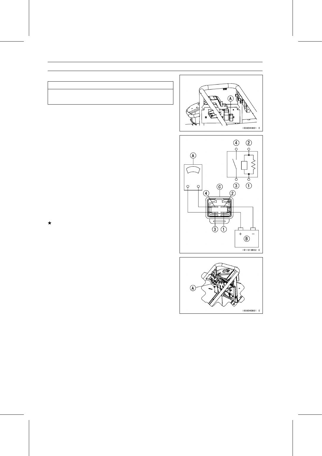
Remove the EPS ECU relay [A] (BK/Y, W/Y, BR, W/BL)
from the tongue and disconnect the connector.

Installation is the reverse of removal.

EPS ECU Relay Inspection

Remove:

EPS ECU Relay (see EPS ECU Relay Removal/Instal-
lation)

Connect the hand tester [A] and a 12 V battery [B] to the
relay [C] as shown.

Special Tool - Hand Tester: 57001-1394

Testing Relay

Hand Tester Range: × 1 Ω
Criteria:

When battery is connected →0 Ω
When battery is disconnected →∞ Ω

Relay Coil Terminals [1] and [2]
Relay Switch Terminals [3] and [4]

If the relay does not work as specified, replace the relay.

Diodes Removal/Installation

Tilt up the front seat and remove the diodes [A].

Installation is the reverse of removal.

STEERING 15-57

EPS (Electric Power Steering) System

Diodes Inspection

Remove the diodes (see Diodes Removal/Installation).

Set the hand tester to the × 10 Ω or × 100 Ω range and
connect it to the diode terminals to check the resistance
in both directions.

Special Tool - Hand Tester: 57001-1394

The resistance should be low in one direction and more
than ten times as much in the other direction. If any diode
shows low or high in both directions, the diode is defective
and the diode unit must be replaced.

NOTE

The actual meter reading varies with the meter used
and the individual diode, but, generally speaking, the
lower reading should be from the zero to one half the
scale.

EPS Fuse 40 A Removal

NOTICE

Before removing the 40 A fuse [A], be sure to dis-
connect the battery cables to avoid electrical shock.

NOTE

The EPS fuse 40 A is installing with bolts to the EPS
fuse box 1 [B].

Disconnect the battery cables (see Battery Removal in the
Electrical System chapter).

Lift up the EPS fuse box 1 [A] with rubber protector [B].

Slide the rubber protector [A].

Unlock the hooks to open the lids [B].

15-58 STEERING

EPS (Electric Power Steering) System

Remove the terminal bolt [A] on both sides.

Unlock the hook to lift up the lid [A].

Pull the EPS fuse 40 A [B] straight out of the EPS fuse
box 1 [C].

EPS Fuse 7.5 A Removal

Tilt up the front seat.

Unlock the hook to lift up the lid [A].

Pull the EPS fuse 7.5 A [A] straight out of the EPS fuse
box 2 [B].

Fuse Installation

If a fuse fails during operation, inspect the EPS system to
determine the cause, and then replace it with a new fuse
of proper amperage.

For EPS fuse 40 A, after installing the lead terminals,
tighten the terminal bolts securely.

Fuse Inspection

Remove the fuse (see EPS Fuse 7.5 A Removal/EPS
Fuse 40 A Removal).

Refer to the Fuse Inspection in the Electrical System
chapter.

For EPS fuse 40 A, there is window for inspection in the
upper surface.

FRAME 16-1

16

Frame

Table of Contents

Exploded View........................................................................................................................

16-3

Seats and Seat Belts ..............................................................................................................

16-12

Front Seat Removal ..........................................................................................................

16-12

Front Seat Installation .......................................................................................................

16-12

Rear Seat Removal...........................................................................................................

16-13

Rear Seat Installation........................................................................................................

16-14

Seat Belt Removal ............................................................................................................

16-14

Seat Belt Installation .........................................................................................................

16-15

Control Panel..........................................................................................................................

16-16

Control Panel Removal .....................................................................................................

16-16

Control Panel Installation ..................................................................................................

16-17

Glove Compartment Removal...........................................................................................

16-17

Front Cargo Compartment......................................................................................................

16-18

Front Cargo Hood Removal ..............................................................................................

16-18

Front Cargo Hood Installation ...........................................................................................

16-18

Front Cargo Hood Cable Adjustment................................................................................

16-19

Front Cargo Compartment Removal.................................................................................

16-19

Front Cargo Compartment Installation..............................................................................

16-19

Cargo Bed ..............................................................................................................................

16-20

Cargo Bed Removal..........................................................................................................

16-20

Cargo Bed Installation.......................................................................................................

16-20

Front, Center and Rear Bars ..................................................................................................

16-22

Front Bar Removal............................................................................................................

16-22

Front Bar Installation.........................................................................................................

16-22

Rear Bar Removal ............................................................................................................

16-22

Rear Bar Installation .........................................................................................................

16-23

Center Bar Removal .........................................................................................................

16-23

Center Bar Installation ......................................................................................................

16-24

Cargo Bed Latch Position Inspection................................................................................

16-24

Cargo Bed Latch Position Adjustment ..............................................................................

16-25

Guard......................................................................................................................................

16-26

Front Guard Removal .......................................................................................................

16-26

Front Guard Installation ....................................................................................................

16-26

Fenders ..................................................................................................................................

16-27

Front Fender Removal ......................................................................................................

16-27

Front Fender Installation ...................................................................................................

16-27

Rear Fender Assembly Removal ......................................................................................

16-27

Covers ....................................................................................................................................

16-29

Front Cover Removal........................................................................................................

16-29

Front Cover Installation.....................................................................................................

16-29

Front Fender Inner Cover Removal ..................................................................................

16-29

Front Fender Inner Cover Installation ...............................................................................

16-30

Radiator Side Cover Removal ..........................................................................................

16-30

Front Side Cover Removal................................................................................................

16-30

Front Side Cover Installation.............................................................................................

16-31

Rear Side Cover Removal ................................................................................................

16-31

Rear Side Cover Installation ............................................................................................

16-31

Middle Cover Removal .....................................................................................................

16-31

Middle Cover Installation...................................................................................................

16-32

Flap Cover Removal .........................................................................................................

16-32


Content   ..  102  103  104  105   ..