Kawasaki Diesel MULE 4010 TRANS 4x4 (KAF950G9). Manual - part 102
 

  Index      Engines     Kawasaki Diesel MULE 4010 TRANS 4x4 (KAF950G9) - service manual


Search            


Content   ..  100  101  102  103   ..


Kawasaki Diesel MULE 4010 TRANS 4x4 (KAF950G9). Manual - part 102


15-48 STEERING

EPS (Electric Power Steering) System

Remove:

Right Glove Compartment (see Glove Compartment Re-
moval in the Frame chapter)
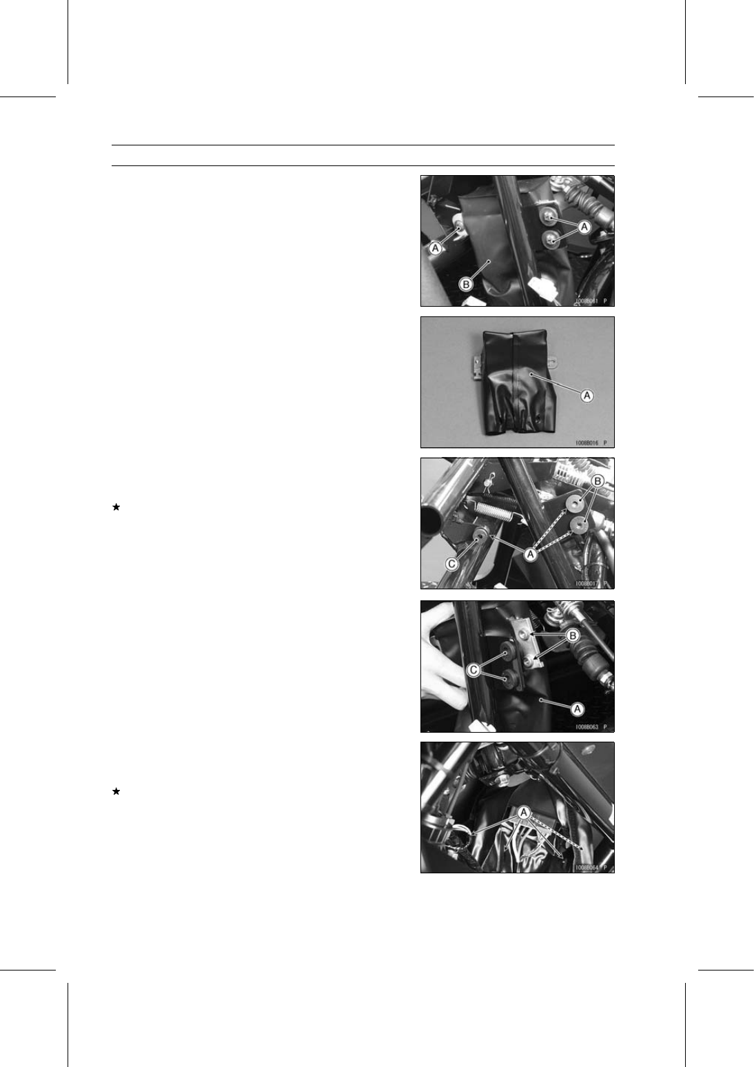
Screws [A]
EPS ECU [B] (with Cover)

Remove the cover [A] from the EPS ECU.

EPS ECU Installation

Check that the rubber dampers [A], collars [B] and wellnut
[C] are in place on the frame.
If the rubber dampers are damaged or deteriorated, re-
place them.

When installing the rubber dampers, note the following.

Install the two rubber dampers of the front side so that the
thin thickness side faces right side.

Do not apply a soap and water solution or rubber lubri-
cant.

Install the cover [A] on the EPS ECU.

Install the cover so that open side faces left side.

Insert the projections [B] of the EPS ECU to the rubber
dampers [C].

Tighten the screws securely.

When installing the band to the cover, note the following.

Pass the band through four slits [A] of the cover.

Bind the cover with the band securely.
If the EPS ECU was replaced, be sure to register the EPS
neutral position(see EPS Neutral Position Registration).

NOTE

The EPS system can not function until the neutral posi-
tion is registered in the new EPS ECU.

STEERING 15-49

EPS (Electric Power Steering) System

EPS ECU Power Supply Voltage Inspection

Remove the band and open the cover (see EPS ECU
Removal).

Visually inspect the EPS ECU connectors [A].
If the connector is clogged with mud or dust, blow it off
with compressed air.
If the connectors are normal, check the terminals of the
EPS ECU connectors.

Turn the main switch OFF.

Disconnect the EPS ECU connectors.

Visually inspect the terminals of the EPS ECU connectors
(main harness and EPS ECU).
If the terminals of the main harness connectors are dam-
aged, replace the main harness.
If the terminals of the EPS ECU connectors are damaged,
replace the EPS ECU.

If the terminals are normal, measure the power supply
voltage of the EPS ECU.

NOTE

Be sure the battery is fully charged.

Set the hand tester [A] to the DC 25 V range and connect
it to the main harness connectors [B].

Special Tool - Hand Tester: 57001-1394

EPS ECU Power Supply Voltage Inspection

Connections:

(I) Hand Tester (+) → W Lead Terminal [C]

Hand Tester (–) → Battery (–) Terminal

(II) Hand Tester (+) → BL/R Lead Terminal [D]

Hand Tester (–) → Battery (–) Terminal

Main Switch OFF:

Connection (I): Battery Voltage
Connection (II): 0 V

Engine Running:

Both Connections: Battery Voltage

If the reading is out of the specification, check the follow-
ing.

EPS Fuse 40 A (see Fuse Inspection)
EPS Fuse 7.5 A (see Fuse Inspection)
Oil Pressure Switch
Oil Pressure Warning Indicator Light
Power Source Wiring and Ground Wiring (Refer to the
next wiring diagram.)

15-50 STEERING

EPS (Electric Power Steering) System

EPS ECU Power Source Circuit

1. EPS ECU
2. EPS Fuse 40 A
3. EPS Fuse 7.5 A
4. Oil Pressure Warning Indicator Light
5. Main Switch

6. Battery 12 V 52 Ah
7. Main Fuse 30 A
8. Fuse Box 2
9. Oil Pressure Switch

EPS Motor Removal

NOTICE

Do not remove the EPS motor [A] from the EPS unit
since it has been adjusted and set with precision at
the factory.

[B] KAF950G9

∼ GC/HA

[C] KAF950GD

STEERING 15-51

EPS (Electric Power Steering) System

EPS Torque Sensor Removal

NOTICE

Do not remove the EPS torque sensor [A] from the
EPS unit since it has been adjusted and set with
precision at the factory.

EPS Unit Removal

NOTICE

The EPS unit [A] has been adjusted and set with pre-
cision at the factory. Therefore, it should be han-
dled carefully, never struck sharply, as with a ham-
mer, or allowed to fall on a hard surface. Be careful
not to get water or mud on the EPS unit.

Remove:

Radiator (see Radiator Removal in the Cooling System
chapter)
Left Radiator Side Cover (see Radiator Side Cover Re-
moval in the Frame chapter)
Water Hoses [A]

Remove the steering gear assembly bracket bolts [B] and
brackets [C].

Remove the mounting bolts [A] of the water pipe.

Remove the universal joint clamp bolt [A].
If the clamp bolt becomes hard to turn, search the posi-
tion that it can be easily turned while turning the steering
wheel slowly.

Pull out the rubber boot [B] upward temporary.


Content   ..  100  101  102  103   ..