Kawasaki Diesel MULE 4010 TRANS 4x4 (KAF950G9). Manual - part 100
 

  Index      Engines     Kawasaki Diesel MULE 4010 TRANS 4x4 (KAF950G9) - service manual


Search            


Content   ..  98  99  100  101   ..


Kawasaki Diesel MULE 4010 TRANS 4x4 (KAF950G9). Manual - part 100


15-40 STEERING

EPS (Electric Power Steering) System

Power Supply Voltage Abnormal (Service Code

11,12)

The usable range of the power supply voltage is 10 V to
16 V.

Check the charging condition (see Alternator Operation
Inspection in the Electrical System chapter).
If the charging condition is normal, check the power sup-
ply voltage (see EPS ECU Power Supply Voltage Inspec-
tion).
If the power supply voltage is good, but the problem still
exists, replace the EPS ECU (see EPS ECU Removal/In-
stallation).

EPS Neutral Position Unregistration (Service

Code 31)

This code appears in the following condition.

When the EPS ECU was replaced and the EPS neutral
position is not registered in the new EPS ECU.

Register the EPS neutral position in the new EPS ECU
(see EPS Neutral Position Registration).

Current Sensor Inspection (Service Code 32)

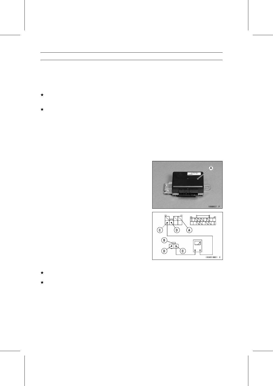
The current sensor is built in the EPS ECU [A]. So, the
current sensor itself can not be inspected.

Turn the main switch OFF.

Disconnect the EPS ECU and EPS motor connectors.

Check the wiring for continuity between main harness
connectors.

Special Tool - Hand Tester: 57001-1394

Wiring Continuity Inspection

EPS ECU Connector [A] ←→

EPS Motor Connector [B]

R Lead [C]
BK Lead [D]

If the wiring is good, check the power supply voltage (see
EPS ECU Power Supply Voltage Inspection).
If the power supply voltage is good, but the problem still
exists, replace the EPS ECU (see EPS ECU Removal/In-
stallation).

STEERING 15-41

EPS (Electric Power Steering) System

FET (Field Effect Transistor) Inspection (Service

Code 33)

The FET is built in the EPS ECU [A]. So, the FET itself
can not be inspected.

Turn the main switch OFF.

Disconnect the EPS ECU and EPS motor connectors.

Check the wiring for continuity between main harness
connectors.

Special Tool - Hand Tester: 57001-1394

Wiring Continuity Inspection

EPS ECU Connector [A] ←→

EPS Motor Connector [B]

R Lead Terminal [C]
BK Lead Terminal [D]

If the wiring is good, check the power supply voltage (see
EPS ECU Power Supply Voltage Inspection).
If the power supply voltage is good, but the problem still
exists, replace the EPS ECU (see EPS ECU Removal/In-
stallation).

Internal Relay Inspection (Service Code 34)

The relay function is included in the EPS ECU [A]. So, the
relay function can not be inspected.

Turn the main switch OFF.

Disconnect the EPS ECU and EPS motor connectors.

Check the wiring for continuity between main harness
connectors.

Special Tool - Hand Tester: 57001-1394

Wiring Continuity Inspection

EPS ECU Connector [A] ←→

EPS Motor Connector [B]

R Lead Terminal [C]
BK Lead Terminal [D]

If the wiring is good, check the power supply voltage (see
EPS ECU Power Supply Voltage Inspection).
If the power supply voltage is good, but the problem still
exists, replace the EPS ECU (see EPS ECU Removal/In-
stallation).

15-42 STEERING

EPS (Electric Power Steering) System

CPU (Central Processing Unit) Inspection (Service

Code 35)

The CPU is built in the EPS ECU [A]. So, the CPU itself
can not be inspected.

Check the power supply voltage (see EPS ECU Power
Supply Voltage Inspection).
If the power supply voltage is good, but the problem still
exists, replace the EPS ECU (see EPS ECU Removal/In-
stallation).

Direction Distinction Circuit Inspection (Service

Code 36)

The direction distinction circuit is built in the EPS ECU
[A]. So, the direction distinction circuit itself can not be
inspected.

Turn the main switch OFF.

Disconnect the EPS ECU and EPS motor connectors.

Check the wiring for continuity between main harness
connectors.

Special Tool - Hand Tester: 57001-1394

Wiring Continuity Inspection

EPS ECU Connector [A] ←→

EPS Motor Connector [B]

R Lead Terminal [C]
BK Lead Terminal [D]

If the wiring is good, check the power supply voltage (see
EPS ECU Power Supply Voltage Inspection).
If the power supply voltage is good, but the problem still
exists, replace the EPS ECU (see EPS ECU Removal/In-
stallation).

Boosting Transformer Circuit Inspection (Service

Code 37)

The boosting transformer circuit is built in the EPS ECU
[A]. So, the boosting transformer circuit itself can not be
inspected.

STEERING 15-43

EPS (Electric Power Steering) System

Turn the main switch OFF.

Disconnect the EPS ECU and EPS motor connectors.

Check the wiring for continuity between main harness
connectors.

Special Tool - Hand Tester: 57001-1394

Wiring Continuity Inspection

EPS ECU Connector [A] ←→

EPS Motor Connector [B]

R Lead Terminal [C]
BK Lead Terminal [D]

If the wiring is good, check the power supply voltage (see
EPS ECU Power Supply Voltage Inspection).
If the power supply voltage is good, but the problem still
exists, replace the EPS ECU (see EPS ECU Removal/In-
stallation).

EPS Torque Sensor Inspection (Service Code 51)

Turn the main switch OFF.

Disconnect the EPS torque sensor connector [A].

Set the hand tester to the × 1Ω range and connect it to
the EPS torque sensor connector [A].

Special Tool - Hand Tester: 57001-1394

Measure the EPS torque sensor resistance.

EPS Torque Sensor Resistance Inspection

Connections:

(I) Y/R Lead [B]

←→ BK/BL Lead [C]

(II) Y/BK Lead [D] ←→ BK/BL Lead [C]

Standard:

Both Connections: Any Reading Resistance

(reference 10

∼ 40 Ω at 20°C

(68°F))

If the reading is infinity (∞) Ω, replace the EPS unit (see
EPS Unit Removal/Installation).


Content   ..  98  99  100  101   ..