Kawasaki Diesel MULE 4010 TRANS 4x4 (KAF950G9). Manual - part 103
 

  Index      Engines     Kawasaki Diesel MULE 4010 TRANS 4x4 (KAF950G9) - service manual


Search            


Content   ..  101  102  103  104   ..


Kawasaki Diesel MULE 4010 TRANS 4x4 (KAF950G9). Manual - part 103


15-52 STEERING

EPS (Electric Power Steering) System

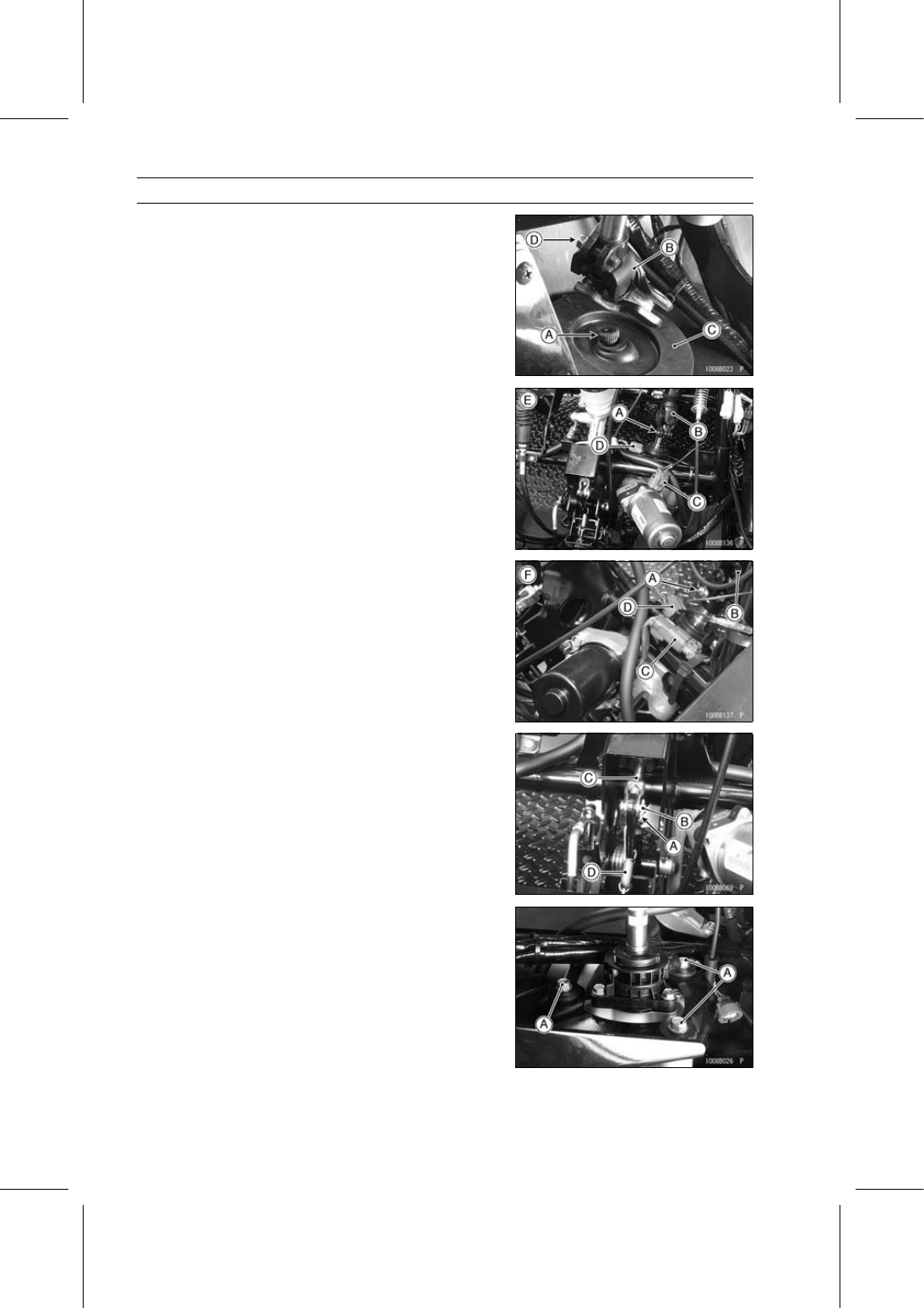
Move the steering gear assembly, and pull off the shaft
[A] from the lower universal joint [B].

Lower the steering gear assembly, and then pull it for-
ward.

Remove:

Rubber Boot [C]
Universal Joint Clamp Bolt [D]
Lower Universal Joint

Remove:

Steering Shaft (see Steering Wheel and Steering Shaft
Removal)
Universal Joint Clamp Bolt [A]
Upper Universal Joint [B]

Disconnect:

EPS Motor Connector [C]
Torque Sensor Connector [D]
[E] KAF950G9

∼ GC/HA

[F] KAF950GD

Remove:

Cotter Pin [A]
Pin [B]
Push Rod [C]
Spring [D]

Remove the EPS unit mounting bolts [A].

STEERING 15-53

EPS (Electric Power Steering) System

Remove the EPS unit [A] downward while pushing down
the brake pedal [B].

Insert the lower shaft to the hole of the under cover and
avoid the upper shaft from the frame.

NOTICE

The EPS unit [A] has been adjusted and set with
precision at the factory. Do not try to disassemble
and repair the EPS unit.

[B] KAF950G9

∼ GC/HA

[C] KAF950GD

EPS Unit Installation

Check that the rubber dampers [A] and upper and lower
collars [B] are in place on the frame.
If the rubber dampers are damaged or deteriorated, re-
place them.

When installing the rubber dampers, note the following.

Install the rubber dampers so that the thin thickness side
faces up.

Do not apply a rubber lubricant.

Install the EPS unit so that the EPS torque sensor [A]
faces upside.

Install the EPS unit mounting bolts [B] and tighten them
temporary.

Install the lower universal joint [C] to the shaft of the EPS
unit.

Install the universal joint clamp bolt [D] while aligning the
notch on the shaft of the EPS unit with the clamp bolt hole
on the lower universal joint, and tighten it temporary.

[E] KAF950G9

∼ GC/HA

[F] KAF950GD

15-54 STEERING

EPS (Electric Power Steering) System

Install the rubber boot [A] on the shaft [B] of the steering
gear assembly temporary.

Install the shaft of the steering gear assembly to the lower
universal joint [C].

Install the universal joint clamp bolt [D] while aligning the
notch on the shaft of the steering gear assembly with the
clamp bolt hole on the lower universal joint, and tighten it
temporary.

Install:

Rubber dampers [E]
Brackets [F]

Apply non-permanent locking agent to the steering gear
assembly bracket bolts [G] and tighten them evenly.

Torque - Steering Gear Assembly Bracket Bolts: 52 N·m

(5.3 kgf·m, 38 ft·lb)

Tighten the EPS unit mounting bolts to the specified
torque.

Torque - EPS Unit Mounting Bolts: 20 N·m (2.0 kgf·m, 15

ft·lb)

[H] KAF950G9

∼ GC/HA

[I] KAF950GD

Install the rubber boot [A] so that the mark (F, Arrow) [B]
faces forward.

Install the upper universal joint [A] to the shaft of the EPS
unit [B].

Install the universal joint clamp bolt (lower) [C] while align-
ing the notch on the shaft of the EPS unit with the clamp
bolt hole on the upper universal joint, and tighten it tem-
porary.

Install the steering shaft [D] to the upper universal joint.

Install the universal joint clamp bolt (upper) [E] while align-
ing the notch on the steering shaft with the clamp bolt hole
on the upper universal joint, and tighten it temporary.

Install the steering shaft mounting bolts [F], washers [G]
and nuts [H].

Tighten all the universal joint clamp bolts to the specified
torque.

Torque - Universal Joint Clamp Bolts: 20 N·m (2.0 kgf·m,

15 ft·lb)

Install the washer [I] (KAF950GD).

[J] KAF950G9

∼ GC/HA

STEERING 15-55

EPS (Electric Power Steering) System

Mount the steering wheel on the steering shaft temporar-
ily.

Adjust the following items.

Steering Wheel Position (see Steering Wheel Position
Adjustment)
Steering Wheel Centering (see Steering Wheel Center-
ing)

Install the removed parts (see appropriate chapters).

Be sure to register the EPS neutral position (see EPS
Neutral Position Registration).

Speed Sensor Removal/Installation

Refer to the Speed Sensor Removal/Installation in the
Electrical System chapter.

Speed Sensor Inspection

Refer to the Speed Sensor Inspection in the Electrical
System chapter.
If the speed sensor is normal, check the wiring for conti-
nuity (Refer to the next wiring diagram.).

Speed Sensor Circuit

1. EPS ECU
2. Speed Sensor
3. Oil Pressure Warning Indicator Light
4. Main Switch

5. Battery 12 V 52 Ah
6. Main Fuse 30 A
7. Fuse Box 2
8. Oil Pressure Switch


Content   ..  101  102  103  104   ..