Kawasaki Diesel MULE 4010 TRANS 4x4 (KAF950G9). Manual - part 97
 

  Index      Engines     Kawasaki Diesel MULE 4010 TRANS 4x4 (KAF950G9) - service manual


Search            


Content   ..  95  96  97  98   ..


Kawasaki Diesel MULE 4010 TRANS 4x4 (KAF950G9). Manual - part 97


15-28 STEERING

EPS (Electric Power Steering) System

Visually inspect the wiring for signs of burning or fraying.
If any wiring is poor, replace the damaged wiring.

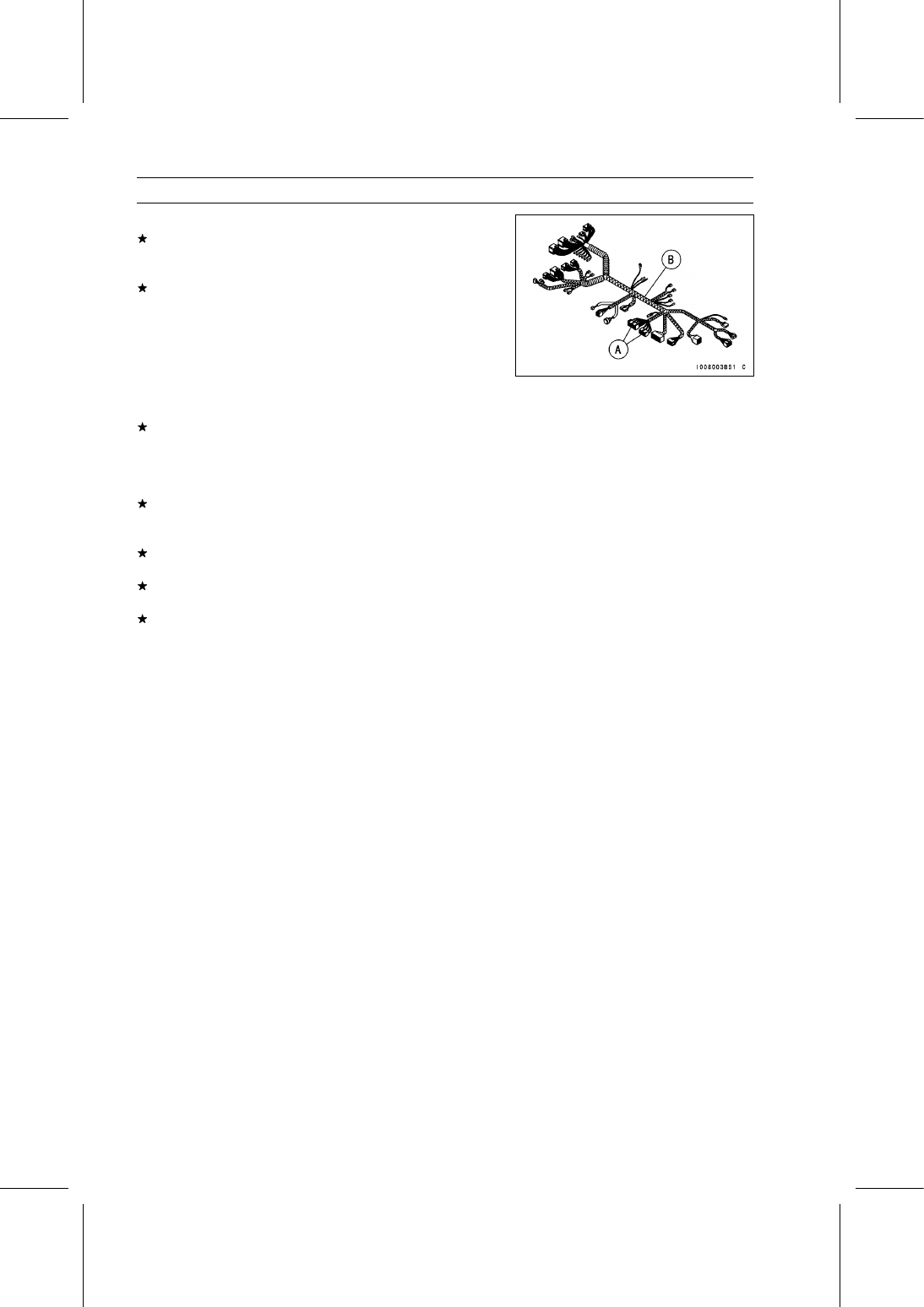
Pull each connector [A] apart and inspect it for corrosion,
dirt and damage.
If the connector is corroded or dirty, clean it carefully. If it
is damaged, replace it.

Check the wiring for continuity.

Use the wiring diagram to find the ends of the lead which
is suspected of being problem.

Connect the hand tester between the ends of the leads.

Special Tool - Hand Tester: 57001-1394

Set the hand tester to the × 1 Ω range, and read the tester.
If the tester does not read 0 Ω, the lead is defective. Re-
place the main harness [B] if necessary.

Narrow down suspicious parts and close in on the faulty
EPS system part by repeating the continuity tests.
If no abnormality is found in the wiring or connectors, the
EPS system parts are the next likely suspects. Check
each part one by one.
If an abnormality is found, replace the affected EPS sys-
tem part.
If all the parts and wirings are good, be sure to inspect the
power supply voltage of the EPS ECU.
If the power supply voltage is good, replace the EPS ECU.

STEERING 15-29

EPS (Electric Power Steering) System

EPS System Diagnosis Flow Chart

15-30 STEERING

EPS (Electric Power Steering) System

Inquiries to Rider

Each rider reacts to problems in different ways, so it is important to confirm what kind of condition
the rider is dissatisfied with.

Try to find out exactly what problem occurs under exactly what conditions by asking the rider; know-
ing this information may help you reproduce the problem in the shop.

The following sample diagnosis sheet will help prevent you from overlooking any keys, so always
use it.

Sample Diagnosis Sheet

Rider name:

Registration No. (license plate No.):

Year of initial registration:

Model:

Engine No.:

Frame No.:

Date problem occurred:

Problem frequency:

Weather:

Mileage:

Steering wheel is heavy.

Steering wheel is too light.

Steering wheel is unbalance.

Steering wheel is naturally turned to one side.

When operating the steering wheel, make vibration or noise.

When operating the steering wheel, the headlight darkens.

EPS system does not operate.

Phenomenon

Other

Engine conditions at
problem

At start-up

After starting

Driving conditions

At high-speed

At low-speed

lights up immediately after engine starts, and goes off after 1 second.

lights up immediately after engine starts, and stays on.

Blinks immediately after engine starts, and stays on.

Does not light up.

EPS warning
indicator light (LED)
conditions

Sometimes lights up.

Self-diagnosis Outline

The EPS self-diagnosis system has two modes and can

be switched to another mode by connecting terminals of the
EPS self-diagnosis system connector [A].

User Mode

The EPS ECU notifies the rider of troubles in EPS system

by lighting the EPS warning indicator light (LED) when EPS
system parts are faulty, and initiates fail-safe function. In
this case, EPS ECU stops the EPS motor operation.

Dealer Mode

The EPS warning indicator light (LED) emits service code

(s) to show the problem (s) by blinking.

STEERING 15-31

EPS (Electric Power Steering) System

Self-diagnosis Procedure

When problem occurs with the EPS system, the EPS
warning indicator light (LED) [A] lights up.

NOTE

Use a fully charged battery when conducting
self-diagnosis.

Otherwise, the EPS warning indi-

cator light (LED) blinks very slowly or does not blink.

Keep the EPS self-diagnosis system connector termi-
nals connected during self-diagnosis, with an auxiliary
lead.

Turn the main switch OFF.

Tilt up the front seat.

Disconnect the EPS self-diagnosis system connector [A].

Connect an auxiliary lead [A] to the terminals of the EPS
self-diagnosis system connector [B] as shown.

Auxiliary Lead Connections:

BL Lead [C] ←→ BK/Y Lead [D]

The BK/Y lead terminal is connected to the battery (–)
terminal.

Start the engine.

Count the blinks of the indicator light to read the service
code (see Service Code Reading).

NOTE

Keep connections of the auxiliary lead until you finish
reading the service code.

If there is no service code, the EPS warning indicator
light (LED) remains lit and service code is not indicated.

Any of the following procedures ends the self-diagnosis
mode.

When the main switch is turned OFF.

When the auxiliary lead is disconnected from the termi-
nals of the EPS self-diagnosis system connector.


Content   ..  95  96  97  98   ..