Kawasaki Diesel MULE 4010 TRANS 4x4 (KAF950G9). Manual - part 96
 

  Index      Engines     Kawasaki Diesel MULE 4010 TRANS 4x4 (KAF950G9) - service manual


Search            


Content   ..  94  95  96  97   ..


Kawasaki Diesel MULE 4010 TRANS 4x4 (KAF950G9). Manual - part 96


15-24 STEERING

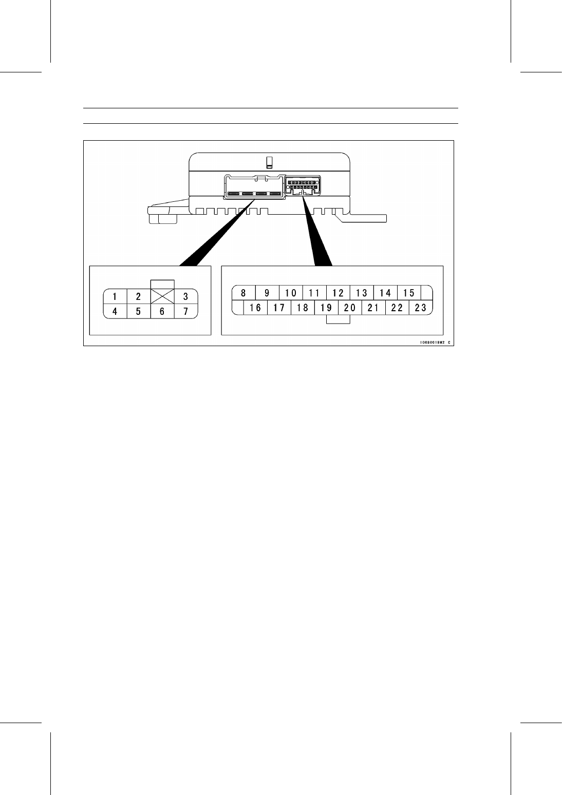
EPS (Electric Power Steering) System

Terminal Names

1. Unused
2. Unused
3. Unused
4. Ground for EPS ECU: BK/Y
5. Power Supply (from Battery): W
6. EPS Motor 1 : BK
7. EPS Motor 2 : R
8. External Communication Line: G
9. EPS Warning Indicator Light (LED): BK/W

10. Unused

11. Unused

12. Speed Sensor Signal: P
13. Unused
14. Unused
15. EPS Torque Sensor Signal 1: Y/BK
16. Power Supply (from Main Switch): BL/R
17. Unused
18. Unused
19. Unused
20. EPS Self-diagnosis System Terminal: BL
21. Unused
22. Ground for EPS Torque Sensor: BK/BL
23. EPS Torque Sensor Signal 2: Y/R

STEERING 15-25

EPS (Electric Power Steering) System

EPS System Servicing Precautions

There are number of important precautions that should be

followed servicing the EPS system.

The EPS system operates while running the engine.

This EPS system is designed to be used with a 12 V bat-
tery as its power source. Do not use any other battery
except for a 12 V battery as a power source.

Do not reverse the battery cable connections. This will
damage the EPS ECU.

To prevent damage to the EPS system parts, do not dis-
connect the battery cables or any other electrical connec-
tions when the main switch ON or while the engine is run-
ning.

Do not short the cables that are directly connected to the
battery positive (+) terminal to the chassis ground.

Do not turn the main switch ON while any of the EPS
electrical connectors are disconnected. The EPS ECU
memorizes service codes.

Do not spray water on the electrical system parts, EPS
system parts, connectors, leads and wiring.

If a transceiver is installed on the vehicle, make sure that
operation of the EPS system is not influenced by electric
wave radiated from the antenna. Locate the antenna as
far as possible away from the EPS ECU.

Whenever the electrical connections of the EPS system
are to be disconnected, first turn the main switch OFF.
Conversely, make sure that all the electrical connections
of the EPS system are firmly reconnected before turning
on the main switch.

When reconnecting the connector, connect these connec-
tors securely until they click [A].

The EPS system parts should never be struck sharply, as
with a hummer, or allowed to fall on a hard surface. Such
a shock to the parts can damage them.

The EPS system parts can not be disassembled. Even if
a fault is found, do not try to disassemble and repair the
EPS system parts, replace it.

With the front wheel lifted from the ground, do not move
the front wheel quickly. An abnormal voltage is generated
and the EPS ECU may be damaged.

Using a fully charged battery. If the power supply voltage
of the EPS ECU becomes 10 V or less, EPS system does
not operate correctly.

15-26 STEERING

EPS (Electric Power Steering) System

There are 40 A and 7.5 A fuses for the EPS system. If
the fuse is blown, the EPS system does not operate. In
this case, the EPS warning indicator light (LED) does not
light up and even if engine is started. Replace the fuse.

WARNING

When replacing the 40 A fuse, first disconnect the
battery cables to avoid electrical shock.

If the EPS system fuses are blown frequently, inspect the
EPS system parts.

If the EPS ECU was replaced, be sure to register the EPS
neutral position (see EPS Neutral Position Registration).
The EPS system can not function until the neutral position
is registered in the new EPS ECU. In this case, the EPS
warning indicator light (LED) blinks immediately after en-
gine starts.

If the following parts were removed or replaced, be sure
to register the neutral position of the EPS (see EPS Neu-
tral Position Registration). If the neutral position does not
register, EPS system does not operate correctly.

EPS Unit
Upper and Lower Universal Joints
Steering Gear Assembly
Steering Knuckles

Do not loosen the following bolts and nuts except repair
work. If the following bolts and nuts were loosened, be
sure to register the EPS neutral position (see EPS Neu-
tral Position Registration). If the neutral position does not
register, EPS system does not operate correctly.

Steering Gear Assembly Bracket Bolts
Tie-Rod End Nuts
Universal Joint Clamp Bolts
EPS Unit Mounting Bolts

Before delivering the vehicle to the customer, be sure to
erase any service codes which might be stored in the EPS
ECU. Using the self-diagnosis function, confirm that the
EPS warning indicator light (LED) lights up (This shows
that there is no service code in the EPS ECU.).

EPS System Troubleshooting Outline

The EPS ECU is equipped with a self-diagnosis function.

When an abnormality in the EPS system occurs, the EPS
ECU lights the EPS warning indicator light (LED) [A] to alert
the rider. In addition, the condition of the problem is stored
in the memory of the EPS ECU as service codes and in
the self-diagnosis mode, the service code is indicated by
the number of times the EPS warning indicator light (LED)
blinks.

STEERING 15-27

EPS (Electric Power Steering) System

If due to a malfunction, the EPS warning indicator light

(LED) remains lit, try to understand the background of the
trouble before starting the repair work. First ask the rider
about the conditions [A] of the trouble, and then start to ex-
amine the cause [B] of the trouble. Do not rely solely on the
self-diagnosis function, use common sense; for example,
check the connections of the connector.

If the problem is with the following parts, the EPS ECU

can not recognize these problem. Therefore, EPS warning
indicator light (LED) does not light up, and service code is
not indicated.

EPS Warning Indicator Light (LED)
EPS ECU Power Source Wiring and Ground Wiring
Speed Sensor

When the repair has been done, the EPS warning indi-

cator light (LED) lights up immediately after engine starts,
and goes off after 1 second. This shows that EPS system is
normal. But, service codes detected once by the EPS ECU
will be memorized in the EPS ECU. Therefore, after main-
tenance work ends, be sure to erase the service codes with
service code erase mode. Do not erase the service codes
during troubleshooting. Wait until all the checks and repair
work are finished to prevent duplication of previous service
codes and unnecessary maintenance work. Before eras-
ing the service codes, record them as problem history. The
problem history can be referred when solving unstable trou-
ble.

Even when the EPS system is operating normally, the

EPS warning indicator light (LED) may light up under strong
electrical interference. If the indicator light lights up, turn the
main switch OFF and then erase the service code.

Much of the EPS system troubleshooting work consists of

confirming continuity of the wiring. The EPS system parts
are assembled and adjusted by the manufacturer, so there
is no need to disassemble or repair them. Replace them as
an assembly.

The basic troubleshooting procedures and precautions

are listed below.

Using a fully charged battery. A fully charged battery is a
must for conducting reliable self-diagnosis function.

Measure coil winding resistance when the EPS system
part is cold (at room temperature).

Check wiring and connections from the EPS ECU con-
nector to the suspected faulty EPS system part, using the
hand tester.

Special Tool - Hand Tester: 57001-1394


Content   ..  94  95  96  97   ..