Kawasaki Diesel MULE 4010 TRANS 4x4 (KAF950G9). Manual - part 94
 

  Index      Engines     Kawasaki Diesel MULE 4010 TRANS 4x4 (KAF950G9) - service manual


Search            


Content   ..  92  93  94  95   ..


Kawasaki Diesel MULE 4010 TRANS 4x4 (KAF950G9). Manual - part 94


15-16 STEERING

Steering Gear Assembly

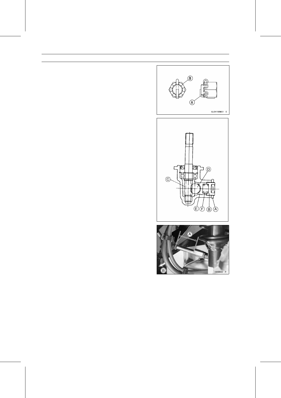
Bend the cotter pin [A] over the nut [B].

Check the toe-in of the front wheels (see Toe-in Adjust-
ment in the Wheels/Tires chapter).

Be sure to register the EPS neutral position (see EPS
Neutral Position Registration).

Steering Gear Preload Adjustment

Loosen the locknut [A].

Tighten the rack guide spring cap [B] to 12.3 N·m (1.25
kgf·m, 109 in·lb) of torque.

Back off the cap 40

∼ 50°.

Tighten the locknut while preventing the cap from turning.

Torque - Rack Guide Spring Cap Locknut: 39 N·m (4.0

kgf·m, 29 ft·lb)

Pinion [C]
Rack [D]
Rack Guide [E]
Spring [F]

Be sure to register the EPS neutral position (see EPS
Neutral Position Registration).

Tie-Rod Length Adjustment

Refer to the Toe-in Adjustment in the Wheels/Tires chap-
ter.

Tie-Rod Length [A]
Front [B]

Steering Joint Dust Boot Inspection

Refer to the Steering Joint Dust Boot Inspection in the
Periodic Maintenance chapter.

STEERING 15-17

Steering Knuckles

Steering Knuckle Removal

Remove:

Front Brake Panel Assembly (see Brake Panel Assy Re-
moval in the Brakes chapter)
Cotter Pin
Tie-Rod End Nut [A]
Tie-Rod End [B] from Steering Knuckle

Remove the tie-rod end from the steering knuckle, using
a suitable joint remover (see Steering Gear Assembly Re-
moval).

NOTICE

Do not loosen the tie-rod end locknuts [C], or the
toe-in of the front wheels will be changed.

Remove:

Brake Hose Retainer [D]
Cotter Pin
Strut Clamp Bolt and Nut [E]

Remove:

Cotter Pin
Front Suspension Arm Joint Nut [A]
Front Suspension Arm Joint from Steering Knuckle

Remove the front suspension arm joint from the steering
knuckle, using a suitable joint remover (see Steering Gear
Assembly Removal).

Remove the steering knuckle [B].

Steering Knuckle Installation

Using a cleaning fluid, clean off any oil or dirt on the ta-
pered portions of the front suspension arm joint and the
tie-rod end joint, and the tapered holes of the steering
knuckle and the front suspension arm. Then dry them
with a clean cloth.

Apply grease to the following portions.

Axle Bearing Grease Seal Lips
Front Suspension Arm Joint Boot Sealing Surfaces [A]

Tighten:

Torque - Strut Clamp Nuts: 98 N·m (10.0 kgf·m, 72.3 ft·lb)

Front Suspension Arm Joint Nuts: 78 N·m (8.0

kgf·m, 58 ft·lb)

Tie-Rod End Nuts: 34 N·m (3.5 kgf·m, 25 ft·lb)

15-18 STEERING

Steering Knuckles

Insert a new cotter pin [A].

NOTE

When inserting the cotter pin, if the slots in the nut do
not align with the cotter pin hole in the axle, tighten the
nut clockwise [B] up to next alignment.

It should be within 30°.

Loosen once and tighten again when the slot goes past
the nearest hole.

Bend the cotter pin [A] over the nut [B].

Check the toe-in of the front wheels (see Toe-in Adjust-
ment in the Wheels/Tires chapter).

Be sure to register the neutral position of the EPS (see
EPS Neutral Position Registration).

Knuckle Bearing Removal

Remove:

Steering Knuckle (see Steering Knuckle Removal)
Grease Seal [A]

Drive the bearing [A] out using a suitable bearing driver
from the bearing driver set.

Special Tool - Bearing Driver Set: 57001-1129

Knuckle Bearing Installation

Press in the bearing until it is bottomed.

Special Tool - Bearing Driver Set [A]: 57001-1129

Replace the grease seal with a new one.

STEERING 15-19

Steering Knuckles

Knuckle Joint Removal

Remove:

Steering Knuckle (see Steering Knuckle Removal)
Circlip [A]

Special Tool - Outside Circlip Pliers [B]: 57001-144

Remove the knuckle joint [A] using a press.

Special Tool - Knuckle Joint Remover [B]: 57001-1619

First, press the knuckle joint until the remover end [C]
touches the knuckle.

Second, move the remover [A] so that its center align with
the center of the knuckle joint.

Press the knuckle joint, and remove it.

Knuckle Joint Installation

Press the knuckle joint [A] until it is bottomed.

Special Tool - Knuckle Joint Driver [B]: 57001-1640

Replace the circlip with a new one.

Special Tool - Outside Circlip Pliers: 57001-144


Content   ..  92  93  94  95   ..