Kawasaki Diesel MULE 4010 TRANS 4x4 (KAF950G9). Manual - part 93
 

  Index      Engines     Kawasaki Diesel MULE 4010 TRANS 4x4 (KAF950G9) - service manual


Search            


Content   ..  91  92  93  94   ..


Kawasaki Diesel MULE 4010 TRANS 4x4 (KAF950G9). Manual - part 93


15-12 STEERING

Steering Wheel and Main Shaft Assembly

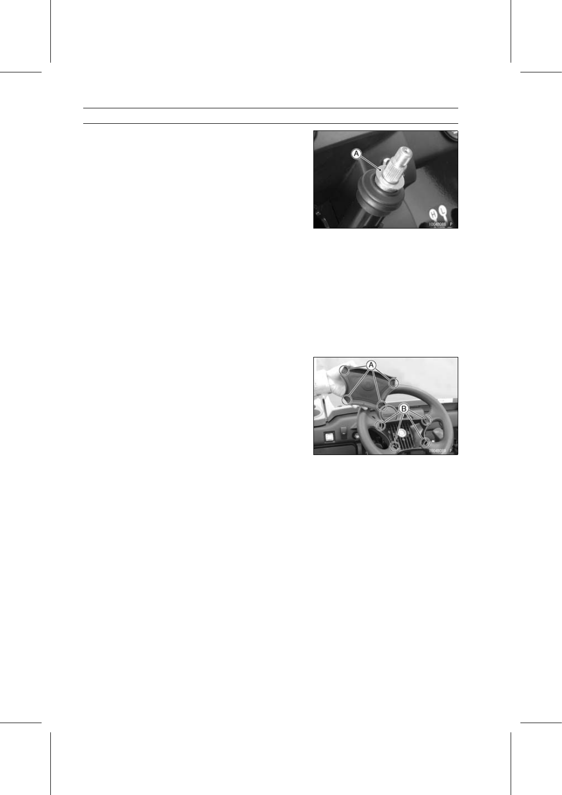
Install the washer [A].

Mount the steering wheel on the steering shaft temporar-
ily.

Adjust the following items.

Steering Wheel Position (see Steering Wheel Position
Adjustment)
Steering Wheel Centering (see Steering Wheel Center-
ing)

Replace the steering wheel mounting nut with a new one.

Tighten:

Torque - Steering Wheel Mounting Nut: 52 N·m (5.3 kgf·m,

38 ft·lb)

Insert the hook portions [A] into the holes [B] of the steer-
ing wheel.

STEERING 15-13

Steering Gear Assembly

Steering Gear Assembly Removal

Remove:

Front Wheels (see Wheel Removal in the Wheels/Tires
chapter)
Radiator (see Radiator Removal in the Cooling System
chapter)
Cotter Pins (Both Sides)
Tie-Rod End Nuts [A] (Both Sides)
Tie-Rod Ends [B] from Steering Knuckles (Both Sides)

NOTICE

Do not loosen the tie-rod end locknuts [C], or the
toe-in of the front wheels will be changed.

Remove the tie-rod end [A] from the steering knuckle, us-
ing a suitable joint remover [B].

Remove:

Left Radiator Side Cover (see Radiator Side Cover Re-
moval in the Frame chapter)
Water Hoses [A]
Horn Ground Lead Terminal [B]

Remove the steering gear assembly bracket bolts [C] and
brackets [D] .

Remove the rubber dumpers [A].

15-14 STEERING

Steering Gear Assembly

Remove the mounting bolts [A] of the water pipe.

Remove the universal joint clamp bolt [A].
If the clamp bolt becomes hard to turn, search the posi-
tion that it can be easily turned while turning the steering
wheel slowly.

Pull out the rubber boot [B] upward temporary.

Move the steering gear assembly, and pull off the shaft
[A] from the lower universal joint [B].

Lower the steering gear assembly, and then pull it for-
ward.

Remove the rubber boot [C].

Remove the steering gear assembly [A] from the vehicle
left side [B].

Steering Gear Assembly Installation

Adjust the following items if necessary.

Steering Gear Preload (see Steering Gear Preload Ad-
justment)
Tie-Rod Length (see Tie-Rod Length Adjustment)

Clean the tapered portion of the tie-rod end joint and the
tapered hole of the steering knuckle, or the tapers will not
fit snugly.

Apply grease to the sealing surface [A] of the tie-rod end
joint boot.

STEERING 15-15

Steering Gear Assembly

Install the rubber boot [A] on the shaft [B] of the steering
gear assembly temporary.

Install the shaft of the steering gear assembly to the lower
universal joint [C].

Install the universal joint clamp bolt [D] while aligning the
notch on the shaft of the steering gear assembly with the
clamp bolt hole on the lower universal joint, and tighten it
temporary.

Install:

Rubber Dampers [E]
Brackets [F]

Apply a non-permanent locking agent to the steering gear
assembly bracket bolts [G] and tighten them evenly.

Torque - Steering Gear Assembly Bracket Bolts: 52 N·m

(5.3 kgf·m, 38 ft·lb)

Tighten the universal joint clamp bolt to the specified
torque.

Torque - Universal Joint Clamp Bolt: 20 N·m (2.0 kgf·m, 15

ft·lb)

[H] KAF950G9

∼ GC/HA

[I] KAF950GD

Install the rubber boot [A] so that the mark (F, Arrow) [B]
faces forward.

Tighten:

Torque - Tie-Rod End Nuts: 34 N·m (3.5 kgf·m, 25 ft·lb)

Insert a new cotter pin [A].

NOTE

When inserting the cotter pin, if the slots in the nut do
not align with the cotter pin hole in the axle, tighten the
nut clockwise [B] up to next alignment.

It should be within 30°.

Loosen once and tighten again when the slot goes past
the nearest hole.


Content   ..  91  92  93  94   ..