Kawasaki Diesel MULE 4010 TRANS 4x4 (KAF950G9). Manual - part 92
 

  Index      Engines     Kawasaki Diesel MULE 4010 TRANS 4x4 (KAF950G9) - service manual


Search            


Content   ..  90  91  92  93   ..


Kawasaki Diesel MULE 4010 TRANS 4x4 (KAF950G9). Manual - part 92


15-8 STEERING

Steering Wheel and Main Shaft Assembly

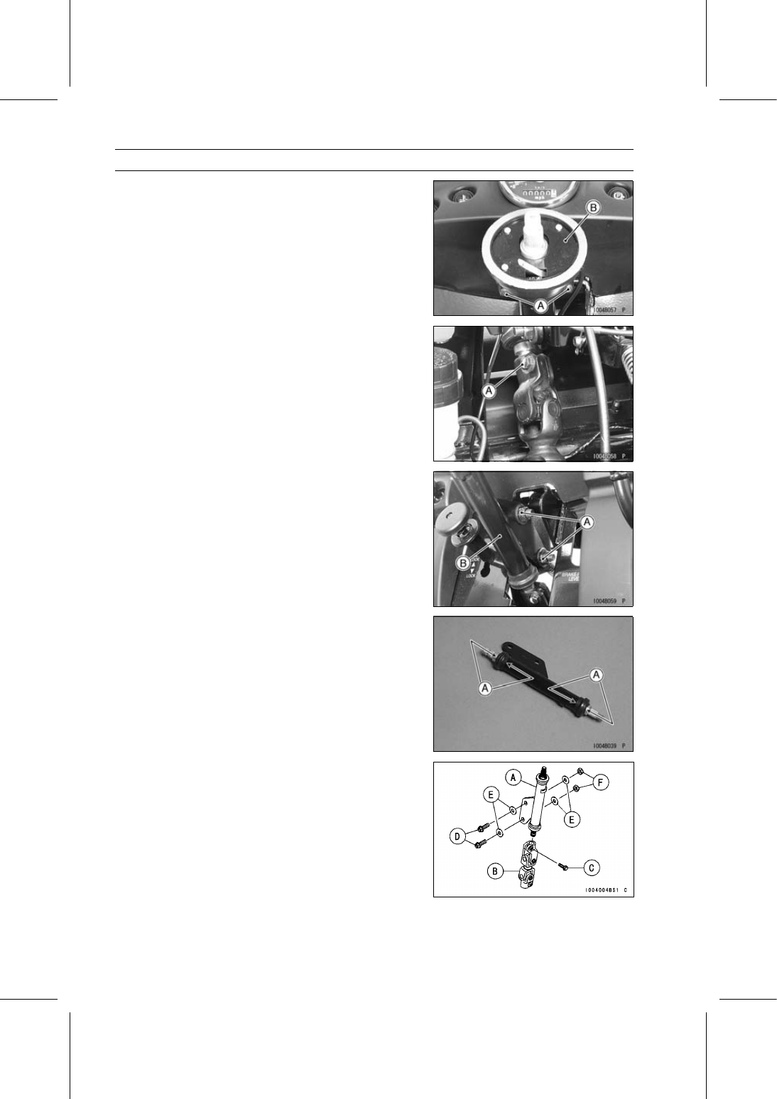
Remove:

Screws [A] and Holder
Horn Switch Contact [B]

Remove:

Front Cargo Compartment (see Front Cargo Compart-
ment Removal in the Frame chapter)
Universal Joint Clamp Bolt [A]

Remove:

Steering Shaft Mounting Bolts, Washers and Nuts [A]
Steering Shaft [B]

Steering Wheel and Steering Shaft Installation

(KAF950G9

GC/HA)

Apply grease to the dust cover lips [A].

Install the steering shaft [A] to the upper universal joint
[B].

Install the universal joint clamp bolt [C] while aligning the
notch on the steering shaft with the clamp bolt hole on the
upper universal joint, and tighten it temporary.

Replace the steering shaft mounting nuts [F] with new
ones.

Install the steering shaft mounting bolts [D], washers [E]
and nuts.

Tighten the universal joint clamp bolt to the specified
torque.

Torque - Universal Joint Clamp Bolts: 20 N·m (2.0 kgf·m,

15 ft·lb)

STEERING 15-9

Steering Wheel and Main Shaft Assembly

Install:

Horn Switch Contact [A]
Holder [B]
Screws [C]

Position the horn switch contact on the projection [D].

Connect the horn switch lead connector [A] and clamp the
bands [B].

Mount the steering wheel on the steering shaft temporar-
ily.

Adjust the following items.

Steering Wheel Position (see Steering Wheel Position
Adjustment)
Steering Wheel Centering (see Steering Wheel Center-
ing)

Replace the self-locknut with a new one.

Tighten:

Torque - Self-lock Nut: 52 N·m (5.3 kgf·m, 38 ft·lb)

Install the horn switch [A] as follows.

Fit the front stoppers [B] in the recesses [C] of the steering
wheel.

Fit the rear stopper [A] in the recess of the steering wheel
and push the rear part until sound click.

15-10 STEERING

Steering Wheel and Main Shaft Assembly

Install the wheel cap [A] so that the arrow mark [B] faces
front and the stoppers [C] fit the recesses [D] of the horn
switch.

Be sure to register the EPS neutral position (see EPS
Neutral Position Registration).

Steering Wheel and Steering Shaft Removal

(KAF950GD)

Clear the hook portions [A] from the steering wheel to
remove the wheel cover [B].

Remove the wheel cover.

Remove:

Steering Wheel Mounting Nut [A] and Washer [B]
Steering Wheel

Remove the washer [A].

Remove:

Front Cargo Compartment (see Front Cargo Compart-
ment Removal in the Frame chapter)
Universal Joint Clamp Bolt [A]

STEERING 15-11

Steering Wheel and Main Shaft Assembly

Remove:

Steering Shaft Mounting Bolts, Washers and Nuts [A]
Steering Shaft [B]

Remove:

Clamp Bolt [A]
Intermediate Shaft [B]

Steering Wheel and Steering Shaft Installation

(KAF950GD)

Apply grease to the dust cover lips [A].

Install the steering shaft [A] to the upper universal joint
[B].

Install the universal joint clamp bolt [C] while aligning the
notch on the steering shaft with the clamp bolt hole on the
upper universal joint, and tighten it temporary.

Replace the steering shaft mounting nuts [F] with new
ones.

Install the steering shaft mounting bolts [D], washers [E]
and nuts.

Tighten:

Torque - Universal Joint Clamp Bolts: 20 N·m (2.0 kgf·m,

15 ft·lb)


Content   ..  90  91  92  93   ..