Kawasaki Diesel MULE 4010 TRANS 4x4 (KAF950G9). Manual - part 90
 

  Index      Engines     Kawasaki Diesel MULE 4010 TRANS 4x4 (KAF950G9) - service manual


Search            


Content   ..  88  89  90  91   ..


Kawasaki Diesel MULE 4010 TRANS 4x4 (KAF950G9). Manual - part 90


14-14 SUSPENSION

Leaf Springs and Dampers

Leaf Spring Installation

When installing the rubber bushings to the leaf spring,
lubricate them with a soap and water solution.

NOTICE

Do not use engine oil or petroleum distillates to lu-
bricate the bushings because they will deteriorate
the rubber.

Install the rear wheel temporarily and ground it to load the
suspension during the mounting nut tightening.

Tighten:

Torque - Leaf Spring Mounting Bolts (Front): 98 N·m (10.0

kgf·m, 72.3 ft·lb)

Leaf Spring Mounting Nuts (Rear): 59 N·m (6.0

kgf·m, 44 ft·lb)

Rear Shock Absorber Mounting Nuts: 59 N·m (6.0

kgf·m, 44 ft·lb)

Apply liquid gasket to the threads of the leaf spring
bracket.

Sealant - Three Bond: 1364D

Replace the damper bracket mounting nuts with new
ones.

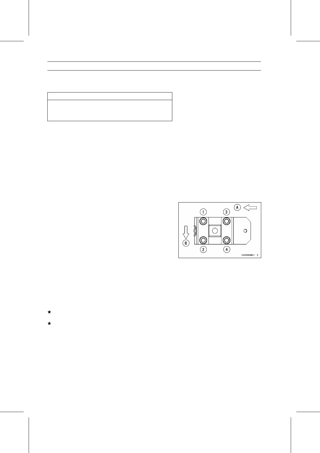
Tighten the damper bracket mounting nuts in the order as
shown in the figure.

Front [A]
Outside [B]

Torque - Damper Bracket Mounting Nuts:

First: 20 N·m (2.0 kgf·m, 15 ft·lb)
Second: 44 N·m (4.5 kgf·m, 32 ft·lb)
Final: 59 N·m (6.0 kgf·m, 44 ft·lb)

Apply brake fluid to the brake pipe nipple threads.

Tighten:

Torque - Brake Pipe Nipples: 18 N·m (1.8 kgf·m, 13 ft·lb)

Bleed the brake line (see Brake Line Air Bleeding in the
Brakes chapter).

Leaf Spring Inspection

Visually inspect the leaf spring for breaks or distortion.
If the leaf spring is damaged in any way, replace it.

Check the rubber bushings in the mounts and the damper.
Replace any bushings or damper that are worn, cracked,
hardened, or otherwise damaged.

STEERING 15-1

15

Steering

Table of Contents

Exploded View...................................

15-2

Specifications ....................................

15-4

Special Tools .....................................

15-5

Steering Wheel and Main Shaft

Assembly ........................................

15-6

Steering Wheel Position

Adjustment ................................

15-6

Steering Wheel Free Play

Inspection..................................

15-6

Steering Wheel Centering............

15-6

Steering Wheel and Steering

Shaft Removal (KAF950G9

GC/HA)......................................

15-7

Steering Wheel and Steering

Shaft Installation (KAF950G9

GC/HA)......................................

15-8

Steering Wheel and Steering

Shaft Removal (KAF950GD).....

15-10

Steering Wheel and Steering

Shaft Installation (KAF950GD)..

15-11

Steering Gear Assembly....................

15-13

Steering Gear Assembly

Removal ....................................

15-13

Steering Gear Assembly

Installation .................................

15-14

Steering Gear Preload

Adjustment ................................

15-16

Tie-Rod Length Adjustment .........

15-16

Steering Joint Dust Boot

Inspection..................................

15-16

Steering Knuckles..............................

15-17

Steering Knuckle Removal...........

15-17

Steering Knuckle Installation........

15-17

Knuckle Bearing Removal............

15-18

Knuckle Bearing Installation.........

15-18

Knuckle Joint Removal ................

15-19

Knuckle Joint Installation .............

15-19

EPS (Electric Power Steering)

System............................................

15-20

EPS System Servicing

Precautions ...............................

15-25

EPS System Troubleshooting

Outline.......................................

15-26

Inquiries to Rider..........................

15-30

Self-diagnosis Outline ..................

15-30

Self-diagnosis Procedure.............

15-31

Service Code Reading .................

15-32

Service Code Erasing ..................

15-32

Service Code Erasing

Procedures................................

15-35

EPS Neutral Position Registration

15-37

Power Supply Voltage Abnormal

(Service Code 11,12) ................

15-40

EPS Neutral Position

Unregistration (Service
Code 31) ...................................

15-40

Current Sensor Inspection

(Service Code 32) .....................

15-40

FET (Field Effect Transistor)

Inspection (Service Code 33)....

15-41

Internal Relay Inspection (Service

Code 34) ...................................

15-41

CPU (Central Processing Unit)

Inspection (Service Code 35)....

15-42

Direction Distinction Circuit

Inspection (Service Code 36)....

15-42

Boosting Transformer Circuit

Inspection (Service Code 37)....

15-42

EPS Torque Sensor Inspection

(Service Code 51) .....................

15-43

EPS Motor Inspection (Service

Code 61) ...................................

15-44

EPS Warning Indicator Light

(LED) Removal..........................

15-45

EPS Warning Indicator Light

(LED) Inspection .......................

15-46

EPS ECU Removal ......................

15-47

EPS ECU Installation ...................

15-48

EPS ECU Power Supply Voltage

Inspection..................................

15-49

EPS Motor Removal ....................

15-50

EPS Torque Sensor Removal ......

15-51

EPS Unit Removal .......................

15-51

EPS Unit Installation ....................

15-53

Speed Sensor Removal/Installa-

tion ............................................

15-55

Speed Sensor Inspection.............

15-55

EPS ECU Relay Removal/Instal-

lation..........................................

15-56

EPS ECU Relay Inspection..........

15-56

Diodes Removal/Installation ........

15-56

Diodes Inspection ........................

15-57

EPS Fuse 40 A Removal .............

15-57

EPS Fuse 7.5 A Removal ............

15-58

Fuse Installation...........................

15-58

Fuse Inspection............................

15-58

15-2 STEERING

Exploded View

STEERING 15-3

Exploded View

Torque

No.

Fastener

N·m

kgf·m

ft·lb

Remarks

1 EPS Unit Mounting Bolts

20

2.0

15

2 Rack Guide Spring Cap Locknut

39

4.0

29

3 Steering Gear Assembly Bracket Bolts

52

5.3

38

L

4 Self-lock Nut

52

5.3

38

R

5 Strut Clamp Nuts

98

10.0

72.3

6 Tie-Rod End Locknuts

44

4.5

32

7 Tie-Rod End Nuts

34

3.5

25

8 Universal Joint Clamp Bolts

20

2.0

15

9. KAF950G9

∼ GC/HA

10. Apply grease on contact plate.

G: Apply grease.

L: Apply a non-permanent locking agent.

R: Replacement Parts


Content   ..  88  89  90  91   ..