Kawasaki Diesel MULE 4010 TRANS 4x4 (KAF950G9). Manual - part 84
 

  Index      Engines     Kawasaki Diesel MULE 4010 TRANS 4x4 (KAF950G9) - service manual


Search            


Content   ..  82  83  84  85   ..


Kawasaki Diesel MULE 4010 TRANS 4x4 (KAF950G9). Manual - part 84


13-14 BRAKES

Brake Drums

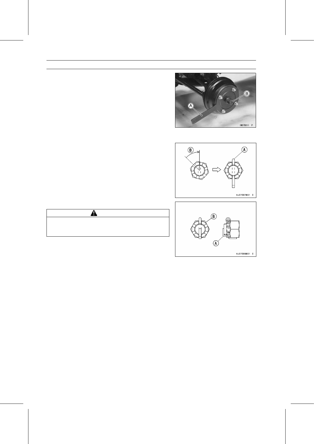
Mount the brake drum holder [A] securely on the drum
studs with the wheel nuts.

Special Tool - Brake Drum Holder: 57001-1325

Using the brake drum pusher [B], and tighten it until the
pusher stops.

Special Tool - Brake Drum Pusher, M18 × 1.5: 57001-1261

And then remove the pusher, install the washer and axle
nut.

Tighten:

Torque - Front Axle Nuts: 196 N·m (20.0 kgf·m, 145 ft·lb)

Rear Axle Nuts: 304 N·m (31.0 kgf·m, 224 ft·lb)

Insert a new cotter pin [A].

NOTE

When inserting the cotter pin, if the slots in the nut do
not align with the cotter pin hole in the axle shaft, tighten
the nut clockwise [B] up to next alignment.

It should be within 30°.

Loosen once and tighten again when the slot goes past
the nearest hole.

Bend the cotter pin [A] over the nut [B].

WARNING

A loose axle nut can lead to an accident resulting in
serious injury or death. Tighten the axle nut to the
proper torque and install a new cotter pin.

Brake Drum Wear

Refer to the Brake Wear Inspection in the Periodic Main-
tenance chapter.

BRAKES 13-15

Brake Panel Assemblies

Brake Panel Assy Removal

(Front Brake Panel)

Remove:

Front Brake Drum (see Brake Drum Removal)
Brake Hose Retainer
Breather Hose [A]
Brake Pipe Nipple [B]
Front [C]

Immediately wipe up any brake fluid that spills.

NOTICE

Brake fluid quickly ruins painted surfaces; any
spilled fluid should be completely wiped up imme-
diately.

Remove the brake panel mounting bolts [A], and then re-
move the brake panel assy [B].

(Rear Brake Panel)

Remove:

Rear Brake Drum [A] (see Brake Drum Removal)
Brake Hose Retainer
Breather Hose [B]
Cotter Pin and Joint Pin [C]
Brake Pipe Nipple [D] (Unscrew)

Immediately wipe up any brake fluid that spills.

NOTICE

Brake fluid quickly ruins painted surfaces; any
spilled fluid should be completely wiped up imme-
diately.

Remove the brake panel mounting bolts [A] and collar [B],
and then remove the brake panel assy [C].

13-16 BRAKES

Brake Panel Assemblies

Brake Panel Assy Installation

Apply lithium grease (NLGI Grade No.2) to the following
portion.

Brake Panel Seating Surface (Between Axle and Panel)

Install the brake panel assy.

Apply a non-permanent locking agent to the threads of
the brake panel mounting bolts.

Torque - Front/Rear Brake Panel Mounting Bolts: 44 N·m

(4.5 kgf·m, 32 ft·lb)

Apply brake fluid to the threads of the brake pipe nipple
and tighten it.

Torque - Brake Pipe Nipples: 18 N·m (1.8 kgf·m, 13 ft·lb)

Install the brake hose retainer.

Bleed the brake line after brake drum installation (see
Brake Line Air Bleeding).

Be sure to check the brake system for good braking
power, no brake drag, and no fluid leakage.

WARNING

After servicing, it takes several applications of the
brake pedal before the brake shoes contact the
drum, which could result in increased stopping
distance and cause an accident resulting in injury
or death. Do not attempt to ride the vehicle until a
firm brake pedal is obtained by pumping the pedal
until the shoes are against the drum.

Inspect the parking brake lever inspection (see Parking
Brake Lever Inspection in the Periodic Maintenance chap-
ter).

Brake Panel Disassembly

(Front Brake Panel)

Remove:

Front Brake Drum (see Brake Drum Removal)
Brake Pipe Nipple and Vent Hose (see Brake Panel Assy
Removal)

Remove the brake shoe springs [A].

While pushing the shoe hold-down spring [B], turn the pin
[C] 90° and remove the shoes [D] individually.

NOTE

Wrap the brake shoes with a clean cloth to protect the
linings from grease or dirt.

Remove the brake panel mounting bolts [E], and then re-
move the brake panel [F].

Front [G]

BRAKES 13-17

Brake Panel Assemblies

(Rear Brake Panel)

Remove:

Rear Brake Drum (see Brake Drum Removal)
Vent Hose [A]
Grommet [B] of Parking Brake Lever Linkage
Brake Pipe Nipple [C] (Unscrew)
Front [D]

Immediately wipe up any brake fluid that spills.

NOTICE

Brake fluid quickly ruins painted surfaces; any
spilled fluid should be completely wiped up imme-
diately.

Remove the brake shoe springs [A].

While pushing the shoe hold-down spring [B], turn the pin
[C] 90° and remove the shoes [D] individually.

NOTE

Wrap the brake shoes with a clean cloth to protect the
linings from grease or dirt.

To prevent the rear pin [E] from dropping into the rear axle
bracket, tape the pin onto the brake panel.

Remove the collar [F] on the rear brake panel.

Front [G]

Remove the following for rear brake panel removal.

Cotter Pin [A]
Joint Pin [B]
Parking Brake Lever Linkage [C]

Remove:

Brake Panel Mounting Bolts [A]
Rear Brake Panel [B]


Content   ..  82  83  84  85   ..