Kawasaki Diesel MULE 4010 TRANS 4x4 (KAF950G9). Manual - part 82
 

  Index      Engines     Kawasaki Diesel MULE 4010 TRANS 4x4 (KAF950G9) - service manual


Search            


Content   ..  80  81  82  83   ..


Kawasaki Diesel MULE 4010 TRANS 4x4 (KAF950G9). Manual - part 82


13-6 BRAKES

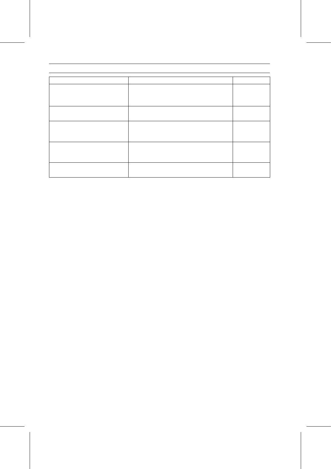
Specifications

Item

Standard

Service Limit

Brake Fluid

Type

DOT3

– – –

Fluid Level

Between upper and lower level lines

– – –

Brake Pedal

Brake Pedal Free Play

2

∼ 10 mm (0.08 ∼ 0.39 in.)

– – –

Brake Drums

Brake Drum Inside Diameter

180.000

∼ 180.160 mm (7.0866 ∼ 7.0929 in.)

180.75 mm

(7.116 in.)

Brake Panel Assemblies

Brake Shoe Lining Thickness

4.5 mm (0.18 in.)

1.0 mm

(0.04 in.)

Parking Brake Lever and Cables

Parking Brake Lever Travel

8

∼ 12 notches (clicks) at 200 N (20 kgf, 44 lb)

– – –

BRAKES 13-7

Special Tools

Clutch Spring Compressor:
57001-1162

Rotor Puller, M16/M18/M20/M22 × 1.5:
57001-1216

Brake Drum Remover:
57001-1260

Brake Drum Pusher, M18 × 1.5:
57001-1261

Brake Drum Holder:
57001-1325

Brake Drum Remover Nuts:
57001-1326

Grease Seal Driver Set:
57001-1629

13-8 BRAKES

Brake Fluid

Brake Fluid Recommendation

Use extra heavy-duty brake fluid only from a container
marked DOT3.

Recommended Brake Fluid

Type:

DOT3

WARNING

Brake fluid that is contaminated by moisture or dirt,
mixed or contains air has a lower boiling point and
can cause the brake to be ineffective or fail, and it
may cause rubber parts to deterioate, resulting in
an accident causing injury or death. Never reuse
old brake fluid. Do not use fluid from a container
that has been left unsealed or that has been open
for a long time. Do not mix two types and brands
of fluid for use in the brake. Don’t leave the reser-
voir cap off for any length of time to avoid moisture
contamination of the fluid. Don’t add or change the
fluid in the rain or when a strong wind is blowing.
If any of the brake line fittings or the bleed valve is
opened at any time, the AIR MUST BE BLED FROM
THE BRAKE LINE.

NOTICE

Brake fluid quickly ruins painted surfaces; any
spilled fluid should be completely wiped up imme-
diately.

Brake Fluid Level Inspection

Refer to the Brake Fluid Level Inspection in the Periodic
Maintenance chapter.

Brake Fluid Change

Refer to the Brake Fluid Change in the Periodic Mainte-
nance chapter.

Brake Line Air Bleeding

Tilt up the front cargo hood and remove the maintenance
cover [A].

Level the reservoir [B] and check that there is plenty of
fluid in the reservoir.

NOTE

The fluid level must be checked several times during the
bleeding operation and replenished as necessary. If the
fluid in the reservoir runs completely out any time dur-
ing bleeding, the bleeding operation must be done over
again from the beginning since air will have entered the
line.

With the reservoir cap off, slowly pump the brake pedal
several times until no air bubbles can be seen rising up
through the fluid from the holes at the bottom of the reser-
voir. This bleeds the air from the master cylinder end of
the line.

BRAKES 13-9

Brake Fluid

Remove the wheel for extra clearance (see Wheel Re-
moval in the Wheels/Tires chapter).

Connect a clear plastic hose [A] to the bleed valve at the
wheel cylinder, and run the other end of the hose into a
container.

Brake Panel [B]

NOTE

Start with the rear left or right wheel and finish with the
front left or right wheel.

Bleed the brake line and the caliper as follows.

Repeat this operation until no more air can be seen com-
ing out into the plastic hose.

1. Pump the brake pedal [A] until it becomes hard, and

apply the brake pedal and hold it.

2. Quickly open and close the bleed valve while holding the

brake pedal applied.

3. Release the brake pedal.

Tighten:

Torque - Bleed Valves: 5.4 N·m (0.55 kgf·m, 48 in·lb)

Repeat the previous step for each wheel.

When air bleeding is finished, add fluid up to the upper
level in the reservoir.

Apply the brake forcefully for a few seconds, and check
for fluid leakage around the fittings.

Install the removed parts (see appropriate chapters).

Torque - Master Cylinder Reservoir Cap: 3.4 N·m (0.35

kgf·m, 30 in·lb)


Content   ..  80  81  82  83   ..