Kawasaki Diesel MULE 4010 TRANS 4x4 (KAF950G9). Manual - part 83
 

  Index      Engines     Kawasaki Diesel MULE 4010 TRANS 4x4 (KAF950G9) - service manual


Search            


Content   ..  81  82  83  84   ..


Kawasaki Diesel MULE 4010 TRANS 4x4 (KAF950G9). Manual - part 83


13-10 BRAKES

Brake Pedal and Master Cylinder

Brake Pedal Play Inspection

Refer to the Brake Pedal Play Inspection in the Periodic
Maintenance chapter.

Master Cylinder Removal

Remove:

Front Cargo Compartment (see Front Cargo Compart-
ment Removal in the Frame chapter)
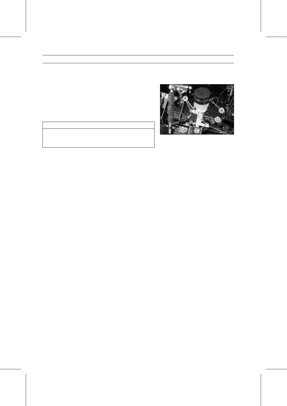
Brake Hose Banjo Bolts [A]
Brake Pipe Nipple [B] (Unscrew)

Immediately wipe up any brake fluid that spills.

NOTICE

Brake fluid quickly ruins painted surfaces; any
spilled fluid should be completely wiped up imme-
diately.

Remove:

Master Cylinder Mounting Bolts [C]
Master Cylinder [D]

Master Cylinder Installation

Use a new flat washer on each side of the brake hose
fitting.

Apply brake fluid to the threads of the brake pipe nipple.

Tighten:

Torque - Brake Hose Banjo Bolts: 25 N·m (2.5 kgf·m, 18

ft·lb)

Brake Pipe Nipples: 18 N·m (1.8 kgf·m, 13 ft·lb)

Bleed the brake line after master cylinder installation.

Adjust the brake pedal play (see Brake Pedal Play Inspec-
tion in the Periodic Maintenance chapter).

Check that the brake line has proper fluid pressure and
no fluid leakage.

Master Cylinder Disassembly/Assembly

Refer to the Brake Master Cylinder Cup and Dust Seal
Replacement in the Periodic Maintenance chapter.

BRAKES 13-11

Brake Pedal and Master Cylinder

Master Cylinder Inspection

Disassemble the master cylinder (see Brake Master
Cylinder Cup and Dust Seal Replacement in the Periodic
Maintenance chapter).

Check that there are no scratches, rust or pitting on the
inside of the cylinder [A] and on the outside of the pistons
[B].
If the cylinder or piston shows any damage, replace them.

Inspect the primary cups [C] and secondary cups [D].
If a cup is worn, damaged, softened (rotted), or swollen,
replace it.
If fluid leakage is noted at the brake push rod, the sec-
ondary cup of the rear piston should be replaced.

Check the dust cover [E] for damage.
If it is damaged, replace it.

Check that the relief [F] and supply [G] ports are not
plugged.
If the small relief port becomes plugged, the brake shoes
will drag on the drum. Blow the ports clean with com-
pressed air.

Check the piston return springs [H] for any damage.
If the spring is damaged, replace it.

13-12 BRAKES

Brake Hoses and Pipes

Brake Hose and Pipe Inspection

Refer to the Brake Hose and Pipe Inspection in the Peri-
odic Maintenance chapter.

Brake Hose and Pipe Replacement

Refer to the Brake Hose and Pipe Replacement in the
Periodic Maintenance chapter.

BRAKES 13-13

Brake Drums

Brake Drum Removal

Remove:

Wheel (see Wheel Removal in the Wheels/Tires chapter)
Cotter Pin [A]
Axle Nut [B]

Loosen the axle nut, while applying the brake, and release
the brake.

You can also loosen the axle nut, using the brake drum
holder (special tool).

Special Tool - Brake Drum Holder: 57001-1325

Be sure to release the parking brake when removing the
rear brake drum.

The brake drums are press-fitted on the axles. Use the
brake drum remover set and rotor puller (special tools) to
remove the drums.

Mount the brake drum remover on the drum studs with
the remover nuts and washers (parts in the remover set).

Special Tools - Rotor Puller, M16/M18/M20/M22 × 1.5 [A]:

57001-1216

Brake Drum Remover [B]: 57001-1260
Brake Drum Remover Nuts [C]: 57001-1326
Washers [D] (57001-1260)

Do not remove the drum bolts. If a drum bolt is damaged,
replace the drum.

Brake Drum Installation

Apply lithium grease (NLGI Grade No.2) to the brake drum
grease seal lips [A] and inside [B] of the drum as shown
in the figure.

Grease Seal [C]
Brake Drum [D]

Do not allow grease to come in contact with the sliding
area of the brake shoes and brake drum.

Wipe off any excess grease.

Install:

Collar [A] (Rear Brake only)
Brake Drum


Content   ..  81  82  83  84   ..