Kawasaki Diesel MULE 4010 TRANS 4x4 (KAF950G9). Manual - part 85
 

  Index      Engines     Kawasaki Diesel MULE 4010 TRANS 4x4 (KAF950G9) - service manual


Search            


Content   ..  83  84  85  86   ..


Kawasaki Diesel MULE 4010 TRANS 4x4 (KAF950G9). Manual - part 85


13-18 BRAKES

Brake Panel Assemblies

Brake Panel Assembly

(Front Brake Panel)

Apply lithium grease (NLGI Grade No.2) to the following
portion.

Brake Panel Seating Surface (Between Axle and Panel)

Install the brake panel and wheel cylinder.

Apply a non-permanent locking agent to the threads of
the brake panel mounting bolts.

Tighten:

Torque - Front Brake Panel Mounting Bolts: 44 N·m (4.5

kgf·m, 32 ft·lb)

Front Wheel Cylinder Mounting Bolts: 10.3 N·m

(1.1 kgf·m, 91 in·lb)

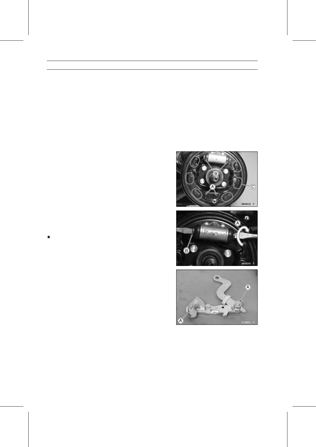
Apply grease to the following portions.

Contact Points [A] of Brake Panel and Brake Shoes
Wheel Cylinder Piston Ends [B]
Brake Shoe Anchor Ends [C]

Apply brake fluid to the threads of the brake pipe nipple
and tighten it.

Torque - Brake Pipe Nipples: 18 N·m (1.8 kgf·m, 13 ft·lb)

The wheel cylinder has a brake shoe clearance adjuster.

Turn [A] either end of the cylinder fully while holding the
other end [B]. Both ends are put into the cylinder.

Check that there is no grease or any oil on the brake shoe.
If there is grease or any oil on the brake shoe, clean off
them with a high flash-point solvent.

Install the brake shoe springs on the original positions
(see Brake Shoe Spring Inspection).

(Rear Brake Panel)

Apply lithium grease (NLGI Grade No.2) to the following
portion.

Brake Panel Seating Surface (Between Axle and Panel)

Install the brake panel and wheel cylinder.

Apply grease to the shoe clearance adjuster pivots [A].

Apply a non-permanent locking agent to the threads of
the brake panel mounting bolts.

Tighten:

Torque - Rear Brake Panel Mounting Bolts: 44 N·m (4.5

kgf·m, 32 ft·lb)

Rear Wheel Cylinder Mounting Nuts: 7.4 N·m (0.75

kgf·m, 65 in·lb)

Apply brake fluid to the thread of the brake pipe nipple
and tighten it.

Torque - Brake Pipe Nipples: 18 N·m (1.8 kgf·m, 13 ft·lb)

Apply grease to the following portions (refer to front brake
above).

Contact Points of Brake Panel and Brake Shoes
Wheel Cylinder Piston Ends
Brake Shoe Anchor Ends

BRAKES 13-19

Brake Panel Assemblies

Install the parking brake lever linkage [A] and the grommet
[B] with the tabs [C] up.

Fit the lips [D] of the grommet as shown in the figure.

Brake Panel [E] (top view of the left rear)

Check that there is no grease or any oil on the brake shoe.
If there is grease or any oil on the brake shoe, clean off
them with a high flash-point solvent.

Install the brake shoe springs on the original positions
(see Brake Shoe Spring Inspection).

The parking brake lever linkage has a brake shoe clear-
ance adjuster.

Push the ratchet [A] forward and then in to reset the shoe
clearance adjuster from the protruding position to its orig-
inal position. The stop [B] sets the position.

Left Parking Brake Lever Linkage [A] of Rear Brake

Ratchet [B]
Protruding Position [C]
Shoe Clearance Adjuster [E]
Front [F]

Left Parking Brake Lever Linkage [A] of Rear Brake

Ratchet [B]
Original Position [D]
Shoe Clearance Adjuster [E]
Front [F]

Pack gaps [A] with grease sparingly.

Install the brake shoe springs on the original positions
(see Brake Shoe Spring Inspection).

13-20 BRAKES

Brake Panel Assemblies

(Front and Rear Brake Panels)

Bleed the brake line after drum installation (see Brake
Line Air Bleeding).

Be sure to check the brake system for good braking
power, no brake drag and no fluid leakage.

WARNING

After servicing, it takes several applications of the
brake pedal before the brake shoes contact the
drum, which could result in increased stopping
distance and cause an accident resulting in injury
or death. Do not attempt to ride the vehicle until a
firm brake pedal is obtained by pumping the pedal
until the shoes are against the drum.

Inspect the parking brake lever inspection (see Parking
Brake Lever Inspection in the Periodic Maintenance chap-
ter).

Wheel Cylinder Removal/Installation

Refer to the Brake Wheel Cylinder Assembly Replace-
ment in the Periodic Maintenance chapter.

Wheel Cylinder Assembly

Before assembly, clean all parts including the wheel cylin-
der with brake fluid or alcohol, and apply brake fluid to the
removed parts and the inner wall of the cylinder.

NOTICE

Use only brake fluid, isopropyl alcohol, or ethyl al-
cohol for cleaning brake parts. Do not use any other
fluid for cleaning these parts. Gasoline, motor oil,
or any other petroleum distillate will cause deterio-
ration of the rubber parts. Oil spilled on any part will
be difficult to wash off completely, and will eventu-
ally deteriorate the rubber used in the brake.

BRAKES 13-21

Brake Panel Assemblies

Wheel Cylinder Inspection

Remove the wheel cylinder (see Brake Wheel Cylinder
Assembly Replacement in the Periodic Maintenance
chapter).

Disassemble the wheel cylinder.

Check that there are no scratches, rust or pitting on the
inside of the cylinder and on the outside of the piston.
If the cylinder or piston shows any damage, replace the
cylinder.

Inspect the cups.
If a cup is worn, damaged, softened (rotted) or swollen,
replace the cylinder.
If fluid leakage is noted at the dust seals, the cylinder
should be replaced to renew the cup.

Check the dust seals for damage.
If they are damaged, replace the cylinder.

Check the spring for any damage.
If the spring is damaged, replace the cylinder.

Check the brake shoe clearance adjuster for damage
(front brake only).
If it shows any damage, replace the cylinder.

Dust Seal [A]
Piston [B]
Cup [C]
Shoe Clearance Adjuster (Front) [D]
Spring (Rear) [E]

Brake Shoe Lining Wear

Refer to the Brake Wear Inspection in the Periodic Main-
tenance chapter.

Brake Shoe Spring Inspection

Visually inspect the brake shoe springs [A] for breaks or
distortion.
If the springs are damaged in any way, replace them.

(Front Brake Panel)

Install the upper shoe spring in the original position
shown, noting the hook direction.

Install the lower spring inside the plate of the shoe.

(Rear Brake Panel)

Install the upper shoe springs in the original position
shown, noting the relative position of the coil to the
parking brake lever linkage.

Install the lower spring inside the plate of the shoe.


Content   ..  83  84  85  86   ..