Kawasaki Diesel MULE 4010 TRANS 4x4 (KAF950G9). Manual - part 75
 

  Index      Engines     Kawasaki Diesel MULE 4010 TRANS 4x4 (KAF950G9) - service manual


Search            


Content   ..  73  74  75  76   ..


Kawasaki Diesel MULE 4010 TRANS 4x4 (KAF950G9). Manual - part 75


12-22 FINAL DRIVE

Bevel Gear Case

Bevel Gear Case Removal

Drain the transmission oil (see Transmission Oil Change
in the Periodic Maintenance chapter).

Remove:

Cargo Bed (see Cargo Bed Removal in the Frame chap-
ter)
Propeller Shaft (see Propeller Shaft Removal)
Right Rear Wheel (see Wheel Removal in the
Wheels/Tires chapter)
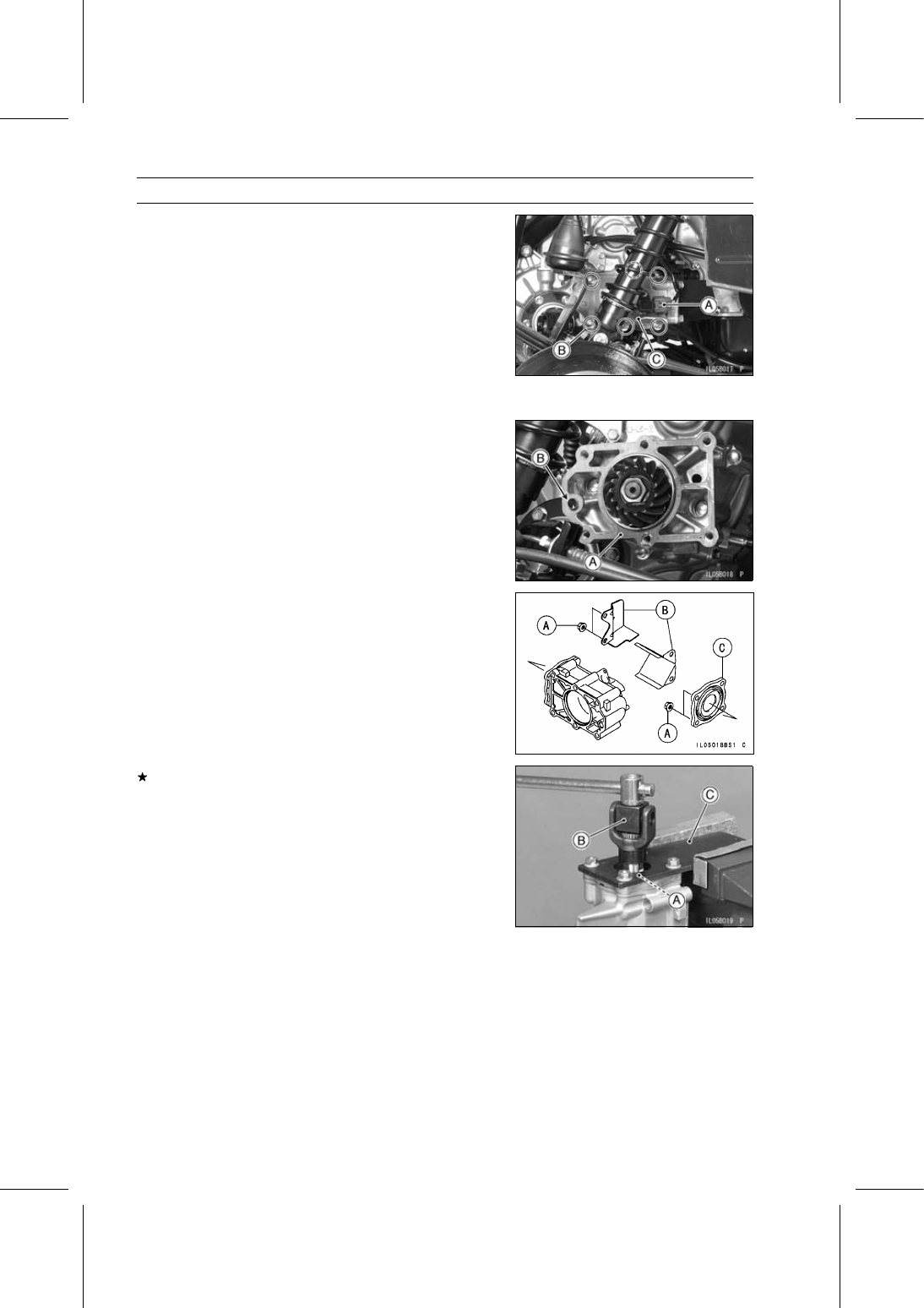
Speed Sensor Lead Connector [A]
Bevel Gear Case Bolts [B]
Bevel Gear Case [C]

Bevel Gear Case Installation

Check and adjust the bevel gear backlash and tooth con-
tact when any of the backlash-related parts are replaced
(see Bevel Gear Adjustment).

Replace the bevel gear case gasket [A] with a new one.

Check to see that the bevel gear case dowel pin [B] is in
place.

Tighten:

Torque - Bevel Gear Case Bolts: 22 N·m (2.2 kgf·m, 16 ft·lb)

Bevel Gear Case Disassembly

Remove:

Speed Sensor (see Speed Sensor Removal in the Elec-
trical System chapter)
Holder Nuts [A]
Covers [B]
Holder [C]

If the driven gear assembly is to be disassembled, loosen
the housing locknut [A].

Special Tools - Pinion Gear Holder [B]: 57001-1281

Socket Wrench [C]: 57001-1363

FINAL DRIVE 12-23

Bevel Gear Case

Remove:

Driven Gear Assembly [A]
Driven Gear Shim(s) [B]

Remove:

Housing Locknut
Bearing Housing [A]

Special Tools - Pinion Gear Holder [B]: 57001-1281

Socket Wrench [C]: 57001-1363

Remove the driven gear shaft nut [A].

Special Tool - Pinion Gear Holder [B]: 57001-1281

Pressing the spring seat [C], remove the driven gear shaft
nut.

Remove the bearing holder [A].

Special Tool - Hexagon Wrench, Hex 40 [B]: 57001-1324

Remove the ball bearings.

Special Tools - Oil Seal & Bearing Remover: 57001-1058

Bearing Driver Set: 57001-1129

Bevel Gear Case Assembly

Install the housing locknut [A] so that the chamfered side
[B] faces to the bearing.

Apply a non-permanent locking agent to the threads of
the following parts.

Driven Gear Shaft Nut
Bearing Holder
Housing Locknut

Tighten:

Torque - Driven Gear Shaft Nut: 108 N·m (11.0 kgf·m, 79.7

ft·lb)

Bearing Holder: 118 N·m (12.0 kgf·m, 87.0 ft·lb)
Housing Locknut: 118 N·m (12.0 kgf·m, 87.0 ft·lb)

12-24 FINAL DRIVE

Bevel Gear Case

Apply grease to the oil seal lips [A].

Tighten:

Torque - Bevel Gear Case Holder Nuts: 25 N·m (2.5 kgf·m,

18 ft·lb)

Drive Bevel Gear Removal

Remove the hi/low gear case (see Hi/Low Gear and Shift
Mechanism Removal in the Transmission chapter).

Hold the transmission gear holder [A] in a vise.

Special Tool - Transmission Gear Holder: 57001-1676

Set the hi/low gear case [A] onto the gear holder.

Remove the drive gear nut [B].

Remove:

Drive Gear [A]
Drive Gear Shim(s) [B]
Drive Gear Shaft [C]

Drive Bevel Gear Installation

Check and adjust the bevel gear backlash and tooth con-
tact when any of the backlash-related parts are replaced
(see Bevel Gear Adjustment).

Apply molybdenum disulfide oil solution to the seating sur-
face of the drive gear nut.

Tighten:

Torque - Drive Gear Nut: 118 N·m (12.0 kgf·m, 87.0 ft·lb)

FINAL DRIVE 12-25

Bevel Gear Case

Bevel Gear Adjustment

In order to prevent one gear from moving away from the

other gear under load, the backlash and tooth contact
pattern 
of the bevel gears must be correct to prevent the
gears from making noise and being damaged.

When replacing any one of the backlash-related parts, be

sure to check and adjust the backlash and tooth contact.
First adjust the backlash, and then tooth contact by replac-
ing shims.

These two adjustments are of critical importance and

must be carried out in the correct sequence, using the
procedures shown.

Backlash Adjustment

Check and adjust the gear backlash when any of the
backlash-related parts are replaced with new ones.

Install the drive gear with the primary shim and assemble
the driven gear with the primary shim. Do not install the
bevel gear case holder during adjustment.

Clean any dirt and oil off the bevel gear teeth.

Install the bevel gear case and tighten the case bolts.

Check the backlash while tightening the case bolts. Stop
tightening them immediately if the backlash disappears
and change the shim to a thinner one.

Hold the driven gear shaft [A] with a vice.

Protect the driven gear shaft with aluminum plates [B].

Set up a dial gauge [C] against the middle point [D] of the
gear dog side [E].

The middle point is position at about 23.5 mm (0.925 in.)
[F] from center.

Gear Dog [G]

To measure the backlash, turn the shaft clockwise and
counterclockwise. The distance between the highest and
lowest gauge reading is the amount of backlash.
If the backlash is not within the limit, replace the shim(s)
at the drive and/or driven gear. To increase backlash, de-
crease the thickness of the shim(s). To decrease back-
lash, increase the thickness of the shim(s).
Change the thickness a little at a time.

Recheck the backlash, and readjust as necessary.

Bevel Gear Backlash

Standard:

0.15

∼ 0.59 mm (0.0059 ∼ 0.0232 in.) (at

middle of gear dog side on drive gear
shaft)


Content   ..  73  74  75  76   ..