Kawasaki Diesel MULE 4010 TRANS 4x4 (KAF950G9). Manual - part 73
 

  Index      Engines     Kawasaki Diesel MULE 4010 TRANS 4x4 (KAF950G9) - service manual


Search            


Content   ..  71  72  73  74   ..


Kawasaki Diesel MULE 4010 TRANS 4x4 (KAF950G9). Manual - part 73


12-14 FINAL DRIVE

Front Final Gear Case

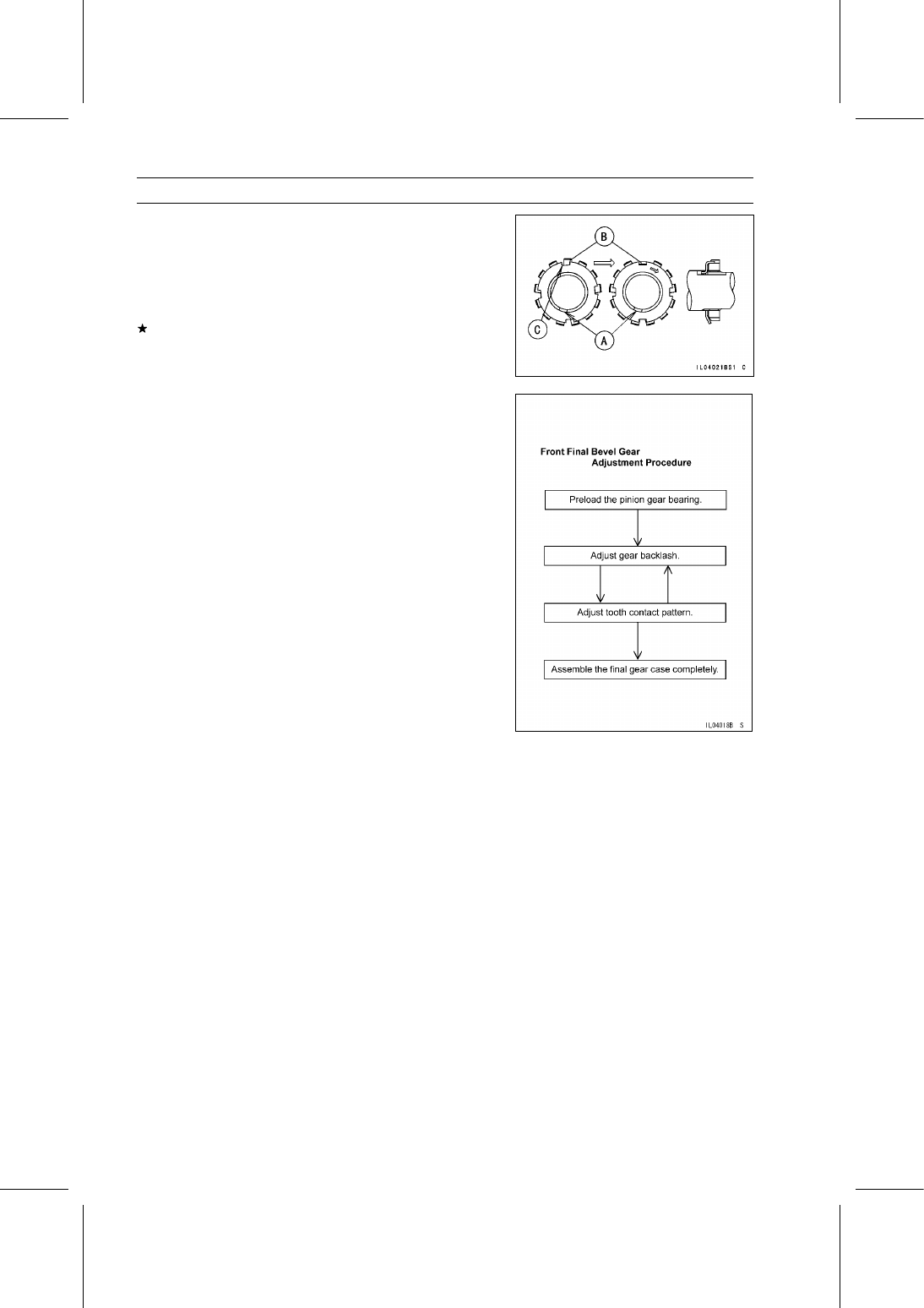
Fit the toothed washer claw [A] into the shaft.

Apply molybdenum disulfide oil solution to the threads
and seating surface of the pinion gear slotted nut, and
tighten it.

Torque - Pinion Gear Slotted Nut: 118 N·m (12.0 kgf·m, 87.0

ft·lb)

If none of the toothed washer tabs [B] align, tighten the
nut further just enough to align one of the tabs with a slot
[C] in the nut.

Bend the tab over the nut.

Front Final Bevel Gear Adjustment

In order to prevent one gear from moving away from the

other gear under load, the tapered roller bearings must be
properly preloaded. Also the backlash (distance one gear
will move back and forth without moving the other gear) and
tooth contact pattern of the bevel gears must be correct to
prevent the gears from making noise and being damaged.

Above three adjustments are of critical importance and

must be carried out following the correct sequence and
method.

When any one of the backlash-related parts are replaced
or the pinion gear nut is loosened; even if the purpose
is not to replace the parts, check and adjust the bearing
preload, the bevel gear backlash, and tooth contact by
replacing shims.

The amount of backlash is influenced by the ring gear
position more than by the pinion gear position.

Tooth contact location is influenced by pinion gear posi-
tion more than by ring gear position.

FINAL DRIVE 12-15

Front Final Gear Case

Bearing Preload Adjustment

Check and adjust the bearing preload in the following
cases.

When any of the parts listed below are replaced with new
ones.

Pinion Gear
Collar
Shim
Tapered Roller Bearings
Pinion Gear Bearing Housing [A]
Oil Seal Collar

When the pinion gear slotted nut [B] is loosened; even if
the nut is not removed.

Install the pinion gear bearing housing and tighten the
pinion gear slotted nut to the specified torque (see Pinion
Gear Unit Assembly).

Do not install the oil seal and O-rings, and do not lock the
washer until the correct bearing preload is obtained.

NOTICE

To start with, choose a shim or collar so that the
bearings are just SNUG with NO play but also with
NO preload.
An over-preload on the bearings could damage the
bearings.

Apply specified gear oil to the bearings, and turn the gears
more than 5 turns to allow the bearings to seat.

Measure the bearing preload. Bearing preload is the force
or torque which is needed to start the gear shaft turning.

NOTE

Preload can be measured either with a spring scale or
a beam-type torque wrench. When measured with a
spring scale, the preload is designated by force (N, kgf,
lb), and when measured with a torque wrench, it is des-
ignated by torque (N·m, kgf·m, in·lb).

12-16 FINAL DRIVE

Front Final Gear Case

FINAL DRIVE 12-17

Front Final Gear Case

If the preload is out of the specified range, replace the
collar and/or shim(s).

To increase preload, decrease the size of the shim(s)
or collar. To decrease preload, increase the size of the
shim(s) or collar.

Change the thickness a little at a time.

Recheck the bearing preload, and readjust as necessary.

Measure the bearing preload using a spring scale.

Using Spring Scale

Pinion Gear Bearing Preload:

1.5

∼ 3.0 N (0.15 ∼ 0.31 kgf, 0.34 ∼ 0.67 lb)

Hook the spring scale [A] on the handle at a point 200
mm (7.87 in.) [B] apart from the center of the gear shaft.
Hold the bearing housing in a vise so that the gear shaft
is vertical.

Apply force to the handle horizontally and at a right angle
to it.

Special Tool - Pinion Gear Holder [C]: 57001-1281

Measure the bearing preload using a torque wrench [A].

Using Torque Wrench

Pinion Gear Bearing Preload Torque:

0.3

∼ 0.6 N·m (0.03 ∼ 0.06 kgf·m, 2.6 ∼ 5.2 in·lb)

Special Tool - Pinion Gear Holder [B]: 57001-1281

Backlash Adjustment

Check and adjust the gear backlash when any of the
backlash-related parts are replaced with new ones.

Clean any dirt and oil off the bevel gear teeth.

Assemble the front final gear case (see Front Final Gear
Case Assembly). Do not install the O-rings during adjust-
ment.

Check the backlash during tightening of the ring gear
cover bolts and stop tightening them immediately if the
backlash disappears. Then, change the ring gear shim
to a thinner one.

Set up a dial gauge against the ditch portion [A] of the
pinion gear slotted nut [B] to check gear backlash shown.

To measure the backlash, move the pinion gear back
and forth while holding the left front axle (ring gear side)
steady. The difference between the highest and the low-
est gauge reading is the amount of backlash.

Measure the backlash at four locations of the nut.


Content   ..  71  72  73  74   ..