Kawasaki Diesel MULE 4010 TRANS 4x4 (KAF950G9). Manual - part 72
 

  Index      Engines     Kawasaki Diesel MULE 4010 TRANS 4x4 (KAF950G9) - service manual


Search            


Content   ..  70  71  72  73   ..


Kawasaki Diesel MULE 4010 TRANS 4x4 (KAF950G9). Manual - part 72


12-10 FINAL DRIVE

Front Final Gear Case

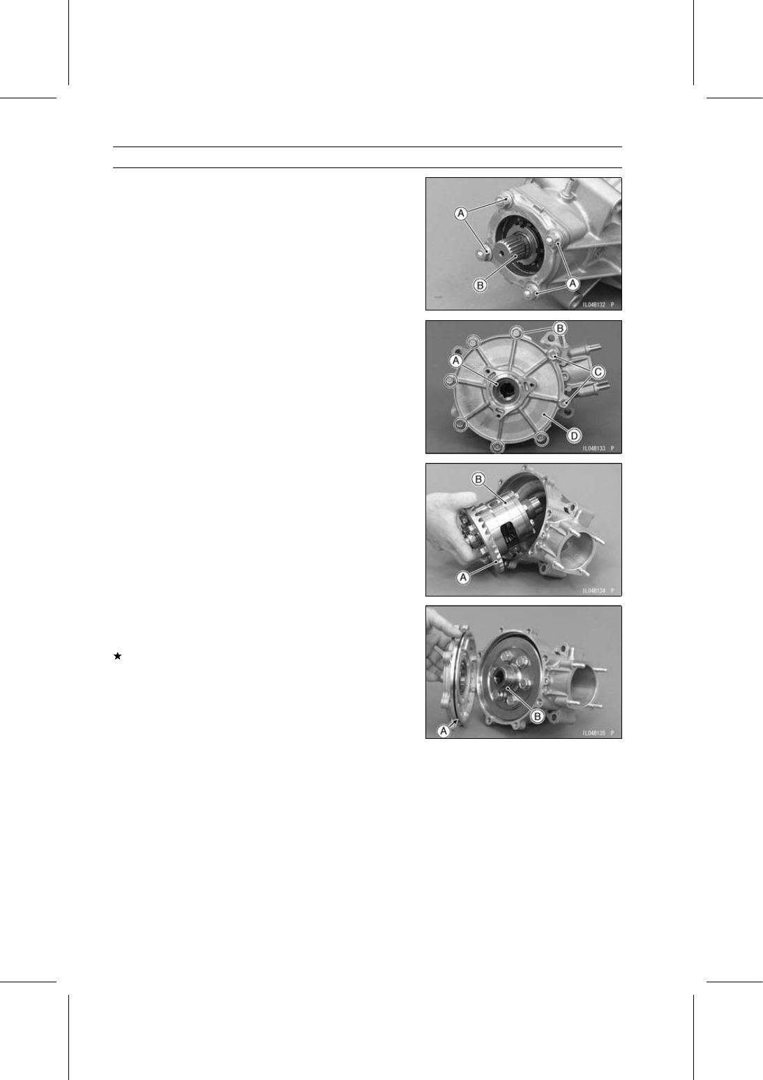
Front Final Gear Case Disassembly

Remove:

Front Final Gear Case (see Front Final Gear Case Re-
moval)
Bearing Housing Nuts [A]
Pinion Gear Unit [B]

Remove the spacers [A] on both sides.

Remove the ring gear cover bolts, starting with the smaller
bolts [B].

Larger Bolts [C]
Ring Gear Cover [D]

Remove the ring gear [A] together with the differential unit
[B].

Front Final Gear Case Assembly

Visually check the pinion gear and ring gear for scoring,
chipping, or other damage.
Replace the bevel gears as a set if either gear is damaged
since they are lapped as a set in the factory to get the best
tooth contact.

Replace the O-ring [A] with a new one.

Apply grease to the new O-ring.

Install:

Differential Unit and Ring Gear
Ring Gear Shim [B]
Ring Gear Cover

First tighten the 10 mm (0.39 in.) bolts, then tighten the 8
mm (0.31 in.) bolts.

Torque - Ring Gear Cover Bolts (M10): 47 N·m (4.8 kgf·m,

35 ft·lb)

Ring Gear Cover Bolts (M8): 25 N·m (2.5 kgf·m, 18

ft·lb)

FINAL DRIVE 12-11

Front Final Gear Case

Install the pinion gear unit with the ring gear side of the
case facing down.

Replace the O-ring [A] with a new one.

Apply grease to the new O-ring.

Align the air vent passage [B] with the hose nipple [C].

Tighten:

Torque - Pinion Gear Bearing Housing Nuts: 25 N·m (2.5

kgf·m, 18 ft·lb)

Adjust:

Front Final Gear Backlash (see Backlash Adjustment)
Front Final Gear Tooth Contact (see Tooth Contact Ad-
justment)

Differential Unit and Ring Gear Disassembly

Remove the differential unit and ring gear (see Front Final
Gear Case Disassembly).

NOTICE

Do not interchange the right and left side parts in
the differential unit.

Remove the following parts to disassemble the differential
unit.

Differential Case Cap Bolts [A]
Differential Case Cap [B]

The clutch plates, springs, spring shims and side gears
come out.

Differential Unit and Ring Gear Assembly

Inspect the clutch plates (see LSD Clutch Plate Inspec-
tion) and the other differential unit parts. Replace any
damaged parts.

Measure and record the thickness of the original clutch
spring shim.

Apply specified gear oil to the differential unit parts.

Note direction and position of the friction plate and the
clutch spring.

Clutch Spring Shim [A]
Clutch Spring [B]
Outside Friction Plate [C]
Steel Plate [D]
Inside Friction Plate [E]

Be sure to assemble the differential unit and inspect the
clutch torque (see LSD Clutch Torque Inspection).

Tighten:

Torque - Differential Case Cap Bolts: 32 N·m (3.3 kgf·m, 24

ft·lb)

12-12 FINAL DRIVE

Front Final Gear Case

If the ring gear is removed, install it as follows.

Insert the pin [A] to the hole of the ring gear [B] and dif-
ferential case [C].

Apply a non-permanent locking agent to the threads of
the ring gear bolts.

Tighten:

Torque - Ring Gear Bolts: 82 N·m (8.4 kgf·m, 61 ft·lb)

LSD Clutch Torque Inspection

After assembling the differential unit and ring gear, check
the LSD clutch torque.

Insert both front axles [A] in the differential unit [B].

Hold the left front axles (ring gear side) with a vise.

Install the hub nut on the other axle.

Measure the clutch torque using a torque wrench [C]

Turn the wrench at 180 degree/5 seconds of rotation
speed.

LSD Clutch Torque

Standard:

7.8

∼ 13 N·m (0.8 ∼ 1.3 kgf·m, 69 ∼ 115

in·lb)

If the clutch torque is out of the specified range, disas-
semble the differential unit (see Differential Unit and Ring
Gear Disassembly) and replace either of the clutch spring
shim.

Also, check the clutch plates and replace them as neces-
sary (see LSD Clutch Plate Inspection).

To increase clutch torque, increase the thickness of the
shim.

Change the thickness a little at a time.

Recheck the clutch torque and readjust as necessary.

Thickness

Part Number

1.2 mm (0.047 in.)

92180-1374

1.3 mm (0.051 in.)

92180-0293

1.4 mm (0.055 in.)

92180-1375

1.5 mm (0.059 in.)

92180-0294

1.6 mm (0.063 in.)

92180-1376

1.7 mm (0.067 in.)

92180-0295

1.8 mm (0.071 in.)

92180-1377

1.9 mm (0.075 in.)

92180-0296

2.0 mm (0.079 in.)

92180-0275

FINAL DRIVE 12-13

Front Final Gear Case

LSD Clutch Plate Inspection

Visually inspect the friction plates and steel plates to see
if they show any signs of seizure, overheating, or uneven
wear.
If any plates show signs of damage, or if the friction plates
have worn past the service limit, replace the friction plates
and steel plates as a set.

Outside Friction Plate [A]
Inside Friction Plate [B]

Outside Friction Plate Thickness

Standard:

2.3

∼ 2.4 mm (0.091 ∼ 0.094 in.)

Service Limit:

2.1 mm (0.083 in.)

Inside Friction Plate Thickness

Standard:

2.7

∼ 2.8 mm (0.106 ∼ 0.110 in.)

Service Limit:

2.4 mm (0.094 in.)

Pinion Gear Unit Disassembly

Remove the pinion gear unit (see Front Final Gear Case
Disassembly).

Pry open the toothed washer tab [A] on the pinion gear
slotted nut [B].

Unscrew the pinion gear slotted nut.

Special Tools - Pinion Gear Holder [A]: 57001-1281

Socket Wrench [B]: 57001-1283

Remove the slotted nut, flat washer and toothed washer.

Pull the pinion gear out of the bearing housing.

Remove the tapered roller bearing inner race as neces-
sary.

Special Tool - Bearing Puller: 57001-135

Pinion Gear Unit Assembly

The pinion gear and ring gear are lapped as a set in the
factory to get the best tooth contact. They must be re-
placed as a set.

Visually inspect the tapered roller bearings for abrasion,
color change, or other damage.
If there is any doubt as to the condition of a bearing, re-
place the bearing housing and the bearings as a set.

Be sure to check and adjust the pinion gear bearing
preload and the bevel gear backlash and tooth contact,
when any of the backlash-related parts are replaced (see
Front Final Bevel Gear Adjustment).

When the pinion gear slotted nut is loosened, even if the
purpose is not to replace the parts, check and adjust the
bearing preload.


Content   ..  70  71  72  73   ..