Kawasaki Diesel MULE 4010 TRANS 4x4 (KAF950G9). Manual - part 65
 

  Index      Engines     Kawasaki Diesel MULE 4010 TRANS 4x4 (KAF950G9) - service manual


Search            


Content   ..  63  64  65  66   ..


Kawasaki Diesel MULE 4010 TRANS 4x4 (KAF950G9). Manual - part 65


10-28 TRANSMISSION

2WD/4WD Shift Mechanism

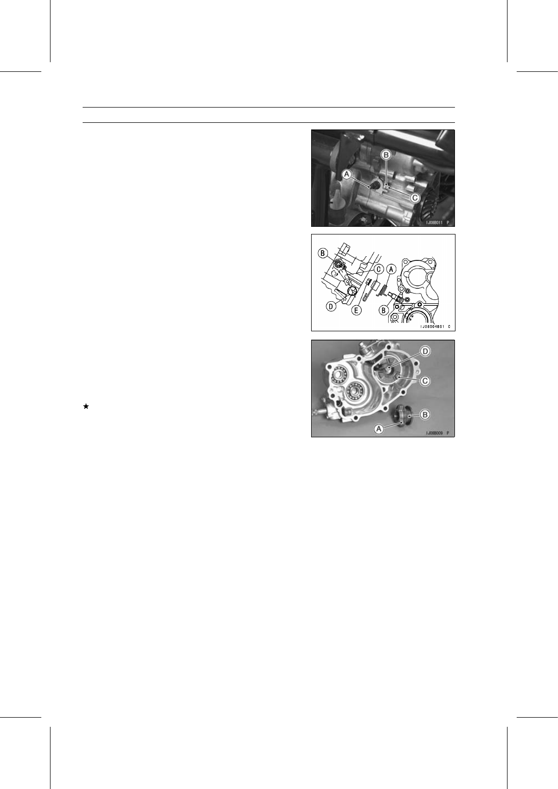
Push the shift shaft [A] as shown in the figure.

Install:

Washer [B]
Shift Shaft Stop Bolt [C]

Tighten:

Torque - Shift Shaft Stop Bolts: 7.8 N·m (0.80 kgf·m, 69

in·lb)

Wipe off any protruding grease.

Install the spring [A].

Turn the shift shaft [B] counterclockwise until it is stop and
hold it.

Install the shift shaft lever [C] on the shift shaft so that the
center of the lever hole aligns with the mark [D] as shown
in the figure.

Tighten the shift shaft lever mounting nut [E].

Hook the spring end.

Check that each gear and shifter spins or slides freely on
its shaft without binding after assembly.

2WD/4WD Shift Mechanism Inspection

Visually inspect the following parts.

Dogs on Shifter [A]
Shifter Groove [B]
Dogs on Drive Bevel Gear Shaft [C]
Shifter Block [D]

If they are damaged or worn excessively, replace them.

Replace parts worn beyond the service limit.

Shifter Block Outside Diameter

Standard:

13.95

∼ 14.00 mm (0.549 ∼ 0.551 in.)

Service Limit:

13.8 mm (0.543 in.)

Shifter Groove Width

Standard:

14.0

∼ 14.2 mm (0.551 ∼ 0.559 in.)

Service Limit:

14.3 mm (0.563 in.)

TRANSMISSION 10-29

Differential Gears and Shift Mechanism

Differential Shift Cable Adjustment

Put the shift lever [A] in the UNLOCK position.

Set the shift shaft lever [A] in the UNLOCK position.

Loosen the adjuster nut [B] until the inner cable is slightly
loosened.

Tighten the adjuster nut [C] securely.

Differential Shift Cable Lubrication

Whenever the shift cable is removed, lubricate the cable

as follows.

Apply a thin coating of grease to the cable ends.

Lubricate the cable with a penetrating rust inhibitor
through the pressure cable luber.

Differential Shift Cable Inspection

With the cable disconnected at both ends, the cable
should move freely [A] within the cable housing.
If the cable movement is not free, if the cable is frayed, or
if the housing is kinked, replace the cable.

Differential Shift Mechanism Removal

Remove:

Drive Shafts and Axles (see Rear Drive Shaft and Axle
Removal in the Final Drive chapter)
Shift Shaft Stop Bolt [A]
Shift Shaft Lever Mounting Nut [B]
Shift Shaft Lever [C]
Spring [D]
Shift Shaft and Arm [E]

10-30 TRANSMISSION

Differential Gears and Shift Mechanism

Differential Shift Mechanism Installation

Insert the shift shaft [A] in the gear case [B].

Replace the O-ring [C] with a new one.

Install the new O-ring and apply molybdenum disulfide
grease to it.

Push the shift shaft [A] as shown in the figure.

Install:

Washer [B]
Shift Shaft Stop Bolt [C]

Tighten:

Torque - Shift Shaft Stop Bolts: 7.8 N·m (0.80 kgf·m, 69

in·lb)

Wipe off any protruding grease.

Install the spring [A].

Turn the shift shaft [B] clockwise until stop and hold it.

Install the shift shaft lever [C] on the shift shaft so that the
lever is position like the figure.

Tighten the shift shaft lever mounting nut [D].

Hook the spring end [E] as shown in the figure.

Differential Shift Mechanism Inspection

Visually inspect the following parts.

Splines on Drive Shaft [A]
Splines on Shifter [B]
Dogs [C] on Shifter
Shifter Groove [D]

Visually inspect the following parts

Shift Arm Pin [A]
Dogs [B] on Differential Gear Housing

If they are damaged or worn excessively, replace them.

TRANSMISSION 10-31

Differential Gears and Shift Mechanism

Replace parts worn beyond the service limit.

Shift Arm Pin Diameter [A]

Standard:

8.4

∼ 8.6 mm (0.331 ∼ 0.339 in.)

Service Limit:

8.3 mm (0.327 in.)

Shifter Groove Width [B]

Standard:

9.0

∼ 9.1 mm (0.354 ∼ 0.358 in.)

Service Limit:

9.2 mm (0.362 in.)

Differential Gear Removal

Split the transmission gear case (see Transmission Gear
Case Splitting).

Remove the differential gear [A].

Remove:

Differential Gear Housing Bolts [A]
Final Gear [B]

Remove:

Housing Cover [A]
Dowel Pin [B]
Side Gear [C]
Spacer [D]

Remove:

Dowel Pins [A]
Retaining Pin [B]
Pinion Gear Shaft [C]
Pinion Gears [D]
Spacers
Side Gear [E]
Spacer


Content   ..  63  64  65  66   ..