Kawasaki Diesel MULE 4010 TRANS 4x4 (KAF950G9). Manual - part 62
 

  Index      Engines     Kawasaki Diesel MULE 4010 TRANS 4x4 (KAF950G9) - service manual


Search            


Content   ..  60  61  62  63   ..


Kawasaki Diesel MULE 4010 TRANS 4x4 (KAF950G9). Manual - part 62


10-16 TRANSMISSION

Transmission and Shift Mechanism

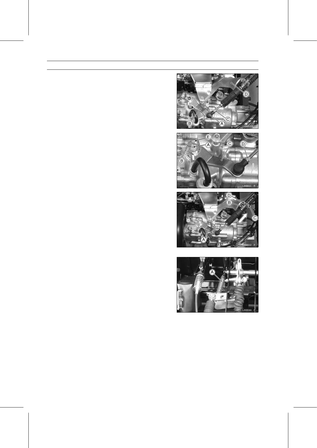
Screw the joint [A] of the shift shaft lever [B] fully into the
transmission shift cable [C] end, and install the cable onto
the bracket [D].

Line up the punch mark [A] on the shift arm, projection
[B] on the transmission case and slit opening in the shift
shaft lever [C].

Tighten:

Shift Shaft Lever Nut [D]
Shift Shaft Lever Clamp Bolt [E]

Hold the shift shaft lever [A] in the neutral position, and
then pull the outer cable [B] lightly forward to remove the
cable free play.

NOTE

If the cable cannot be adjusted, move the slit opening in
the shift shaft lever one notch to right side of the punch
mark on the shift arm.

Tighten:

Transmission Shift Cable Adjuster Nut [C]
Transmission Shift Cable Adjuster Nut [D]

Install the spring [A] back onto the shift shaft lever assem-
bly.

Check the shift lever position (see Shift Lever Position
Inspection).

TRANSMISSION 10-17

Transmission and Shift Mechanism

Shift Lever Position Inspection

Start the engine and put the shift lever in “N” (NEUTRAL)
or “L” (LOW) position.

Move the shift lever [A] slowly to the direction of the arrow
on the figure. At this time, increase the engine speed
slightly.

Check the grinding noise at the specified positions [B] and
[C].
If the position of the grinding noise is far from the specified
position, adjust the shift lever position (see Shift Lever
Position Adjustment).

Shift Lever Position Adjustment

Loosen the hi/low shift cable adjuster nuts [A] and [B].

Adjust the hi/low shift cable and set the transmission shift
lever [A] in the correct position as follows.

The gap [B] between the shift lever and panel is approxi-
mate 1.5 mm (0.06 in.).

When the outer cable moving forward, the shift lever
moves left side.

When the outer cable moving rearward, the shift lever
moves right side.

Tighten the hi/low shift cable adjuster nuts.

Loosen the transmission shift cable adjuster nuts [A] and
[B].

Adjust the transmission shift cable and set the transmis-
sion shift lever [A] in the correct position as follows.

When the shift lever moving to right and left, the gaps
between [B] and [C] are same.

When the outer cable moving forward, the shift lever
moves upward.

When the outer cable moving rearward, the shift lever
moves downward.

Tighten the transmission shift cable adjuster nuts.

10-18 TRANSMISSION

Transmission and Shift Mechanism

Transmission Shift Cable Inspection

With the cable disconnected at both ends, the cable
should move freely within the cable housing.
If the cable movement is not free, if the cable is frayed, or
if the housing is kinked, replace the cable.

Transmission Removal

Remove:

Transmission Case (see Transmission Case Removal)
Hi/Low Shift Gear (see Hi/Low Gear and Shift Mecha-
nism Removal)
Speedometer Gear (see 2WD/4WD Shift Mechanism
Removal)

Split the transmission case (see Transmission Case Split-
ting)

Remove:

Differential Gear Assembly (see Differential Gear Re-
moval)
Drive Shaft [A]
Washers [B]
Drive Shaft Reverse Sprocket [C]
Drive Chains [D]

Remove:

Shift Arm Positioning Bolt Assembly [A]
Retaining Pin [B]

Lift the shift arm [C] and remove the shifter [D].

Remove:

Drive Shaft (Outer) [A] and Drive Shaft Forward Gear [B]
Shifter Block [C]
Shift Arm [D]

TRANSMISSION 10-19

Transmission and Shift Mechanism

Remove the driven shaft assembly [A].

Remove:

Circlips [A]
Driven Shaft Reverse Sprocket [B]
Driven Shaft Forward Gear [C]
Driven Shaft [D]

Special Tool - Outside Circlip Pliers: 57001-144

Transmission Installation

Replace all circlips that were removed with new ones.

NOTE

Always install the circlips [A] so that the opening [B] is
aligned with a spline groove. To install a circlip without
damage, first fit the circlip onto the shaft [C] and then
expand it just enough to install. Hence, use a suitable
gear to push the circlip into place.

Apply transmission oil to the following parts.

Drive and Driven Shafts
Forward Gears
Reverse Sprockets
Drive Chains

Apply grease to the following parts.

Oil Seal Lips
Shift Arm Positioning Ball and Spring

Install the shifter [A] so that the groove [B] is away from
the forward gear [C].

Tighten:

Torque - Shift Arm Positioning Bolt: 37 N·m (3.8 kgf·m, 27

ft·lb)


Content   ..  60  61  62  63   ..