Kawasaki Diesel MULE 4010 TRANS 4x4 (KAF950G9). Manual - part 61
 

  Index      Engines     Kawasaki Diesel MULE 4010 TRANS 4x4 (KAF950G9) - service manual


Search            


Content   ..  59  60  61  62   ..


Kawasaki Diesel MULE 4010 TRANS 4x4 (KAF950G9). Manual - part 61


10-12 TRANSMISSION

Transmission Case

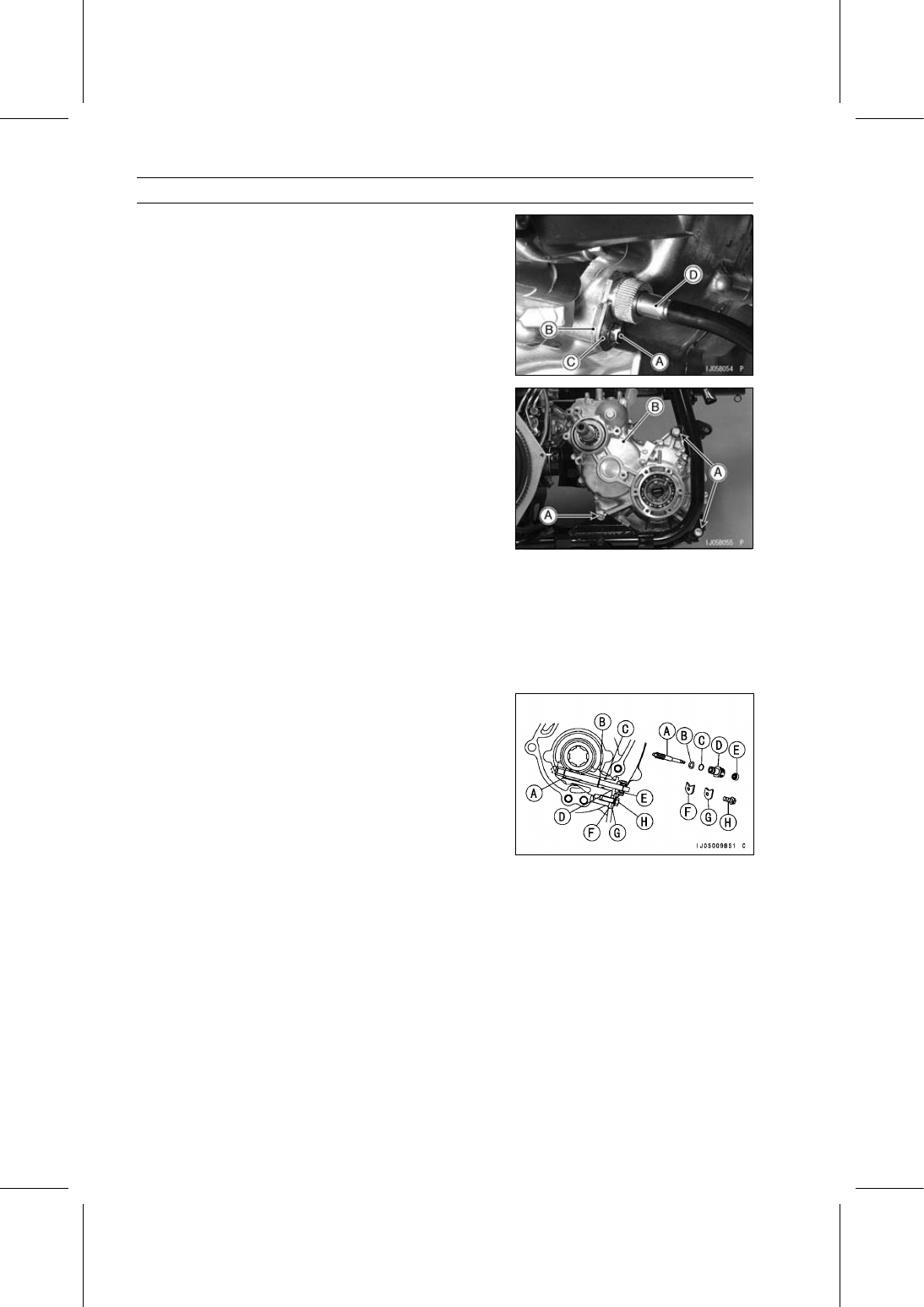
Remove:

Bolt [A]
Thick Holder [B]
Thin Holder [C]
Speedometer Cable Lower End [D]

Remove:

Transmission Case Mounting Bolts and Nuts [A]
Transmission Case [B]

Transmission Case Installation

Adjust the transmission case mounting position (see En-
gine Installation in the Engine Removal/Installation chap-
ter).

Tighten:

Torque - Transmission Case Mounting Nuts: 44 N·m (4.5

kgf·m, 32 ft·lb)

Install:

Speedometer Gear [A]
Washer [B]
New O-ring [C]
Bushing [D]
Oil Seal [E]
Thick Holder [F]
Thin Holder [G]
Bolt [H]

Adjust:

Transmission Oil (see Transmission Oil Change in the
Periodic Maintenance chapter)
Transmission Shift Cable (see Shift Lever Position Ad-
justment)
Differential Shift Cable (see Differential Shift Cable Ad-
justment)
Hi/Low Shift Cable (see Shift Lever Position Adjustment)
2WD/4WD Shift Cable (see 2WD/4WD Shift Cable Ad-
justment)

TRANSMISSION 10-13

Transmission Case

Transmission Case Splitting

Remove:

Transmission Case (see Transmission Case Removal)
Bevel Gear Case (see Bevel Gear Case Removal in the
Final Drive chapter)
Hi/Low Gear Case (see Hi/Low Gear and Shift Mecha-
nism Removal)
Cable Bracket [A]
Bolts [B]
Left Transmission Case [C]

Transmission Case Assembly

Check to see that the transmission case dowel pins [A]
are in place. If any one of them has been removed, re-
place it with a new one.

Apply liquid gasket to the transmission case mating sur-
face.

Sealant - Liquid Gasket, TB1105B: 92104-002

Apply grease to the oil seal lips

Tighten:

Torque - Transmission Case Bolts: 8.8 N·m (0.90 kgf·m, 78

in·lb)

10-14 TRANSMISSION

Transmission and Shift Mechanism

Transmission and Hi/Low Shift Cables Installation

Remove one side of the spring [A] from the shift shaft lever
assembly.

Put the shift lever [A] in the “L” (LOW) position.

Using the shift shaft lever [A] temporarily set the shift arm
[B] in forward or reverse position as shown in the figure.

Put the differential shift lever [A] in “LOCK” position.

Turn the hi/low shift shaft lever [A] clockwise while turning
the drive shafts (wheels) until the lever engages low gear.

TRANSMISSION 10-15

Transmission and Shift Mechanism

Screw the joint [A] of the shift shaft lever [B] fully into the
hi/low shift cable [C] end, and install the cable onto the
bracket [D].

Line up the punch mark [A] on the shift arm, projection
[B] on the transmission case and slit opening in the shift
shaft lever [C].

Tighten:

Shift Shaft Lever Nut [D]
Shift Shaft Lever Clamp Bolt [E]

Hold the shift shaft lever [A] in the low range position
turning fully clockwise, and then push the outer cable [B]
lightly rearward to remove the cable free play.

Tighten:

Hi/Low Shift Cable Adjuster Nut [C]
Hi/Low Shift Cable Adjuster Nut [D]

Put the shift lever [A] in the center of right and left at “N”
(NEUTRAL) position, and hold it at the location [B].

Install suitable plates [C] between the shift lever and lower
and upper side of the gate in order to fix the shift lever.

Using the shift shaft lever [A] temporarily set the shift arm
[B] in neutral position as shown in the figure.


Content   ..  59  60  61  62   ..