Kawasaki Diesel MULE 4010 TRANS 4x4 (KAF950G9). Manual - part 56
 

  Index      Engines     Kawasaki Diesel MULE 4010 TRANS 4x4 (KAF950G9) - service manual


Search            


Content   ..  54  55  56  57   ..


Kawasaki Diesel MULE 4010 TRANS 4x4 (KAF950G9). Manual - part 56


9-26 CRANKSHAFT/CRANKCASE

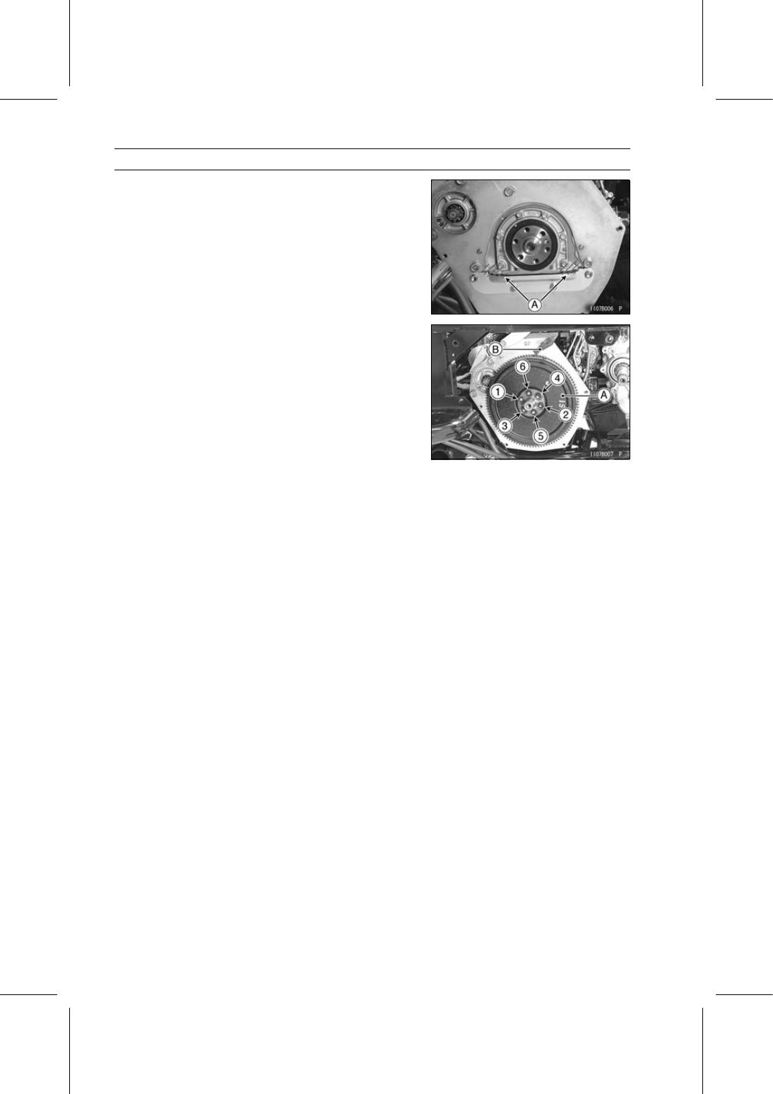
End Plate

Apply liquid gasket [A] to the mating surface as shown in
the figure.

Sealant - Three Bond: 1207F

Install the flywheel [A] and coupling.

Apply a non-permanent locking agent to the threads of
the flywheel mounting bolts.

Using the flywheel holder [B], hold the flywheel.

Special Tool - Flywheel Holder: 57001-1438

Tighten the flywheel mounting bolts following the tighten-
ing sequence as shown in the figure.

Torque - Flywheel Mounting Bolts:

First

32 N·m (3.3 kgf·m, 24 ft·lb)

Final

44 N·m (4.5 kgf·m, 32 ft·lb)

Install the removed parts (see appropriate chapters).

CRANKSHAFT/CRANKCASE 9-27

Oil Seal Retainer

Oil Seal Replacement

Remove:

Oil Seal Retainer [A] (see Crankshaft Removal)
Oil Seal [B]

Replace the oil seal with new one.

Apply engine oil to the outside of the oil seal.

Press in a new oil seal so that the seal surface is flush
with the end of the hole.

Special Tool - Retainer Oil Seal Driver [A]: 57001-1437

Apply high-temperature grease to the oil seal lips.

9-28 CRANKSHAFT/CRANKCASE

Pistons and Crankcase

Piston Removal

Remove:

Connecting Rod (see Connecting Rod Removal)
Snap Rings [A]

Special Tool - Inside Circlip Pliers: 57001-143

Remove the piston pin.

Special Tool - Piston Pin Puller Assembly [A]: 57001-910

Remove the piston.

Carefully spread the ring opening with your thumbs and
then push up on the opposite side of the ring [A] to remove
it.

Remove the 3-piece oil ring with your thumbs in the same
manner.

Piston Installation

Apply engine oil to the piston pin.

Align the arrow [A] on the piston and ID mark [B] on the
connecting rod.

Install:

Piston Pin
New Snap Rings

Special Tool - Inside Circlip Pliers: 57001-143

Install the oil ring coil expander making sure the wire is
completely inserted into the coil expander.

CRANKSHAFT/CRANKCASE 9-29

Pistons and Crankcase

Install:

Oil Ring Coil Expander
Oil Ring [A]
Second Ring [B]
Top Ring [C]

The second and top rings must be installed with the “T”
mark [D] facing up.

Position each piston ring end gap as shown in the figure.

Arrow [A]
Top Ring End Gap [B]
Second Ring End Gap [C]
Oil Ring End Gap [D]

Crankcase Removal

Remove:

Connecting Rods (see Connecting Rod Removal)
Crankshaft (see Crankshaft Removal)
Crankcase [A]

Crankcase Warp

Clean the crankcase.

Lay a straightedge [A] across the upper surface of the
crankcase at several different points, and measure the
warp by inserting a thickness gauge [B] between the
straightedge and the crankcase.

Crankcase Warp

Service Limit:

0.08 mm (0.0031 in.)

If the warp exceeds the service limit, the crankcase may
be resurfaced to the service limit of the crankcase height
[A].

Crankcase Height

Standard:

238.70

∼ 239.30 mm (9.3976 ∼ 9.4212 in.)

Service Limit: 238.60 mm (9.3937 in.)

If the height is less than the service limit, replace the
crankcase.


Content   ..  54  55  56  57   ..