Kawasaki Diesel MULE 4010 TRANS 4x4 (KAF950G9). Manual - part 55
 

  Index      Engines     Kawasaki Diesel MULE 4010 TRANS 4x4 (KAF950G9) - service manual


Search            


Content   ..  53  54  55  56   ..


Kawasaki Diesel MULE 4010 TRANS 4x4 (KAF950G9). Manual - part 55


9-22 CRANKSHAFT/CRANKCASE

Crankshaft and Connecting Rods

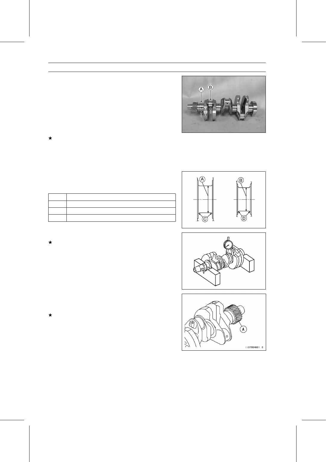
Check the crankshaft main journals and crankpins for
wear and taper.

Crankshaft Main Journal Diameter [A]

Standard:

41.976

∼ 42.000 mm (1.6526 ∼ 1.6535 in.)

Crankshaft Crankpin Diameter [B]

Standard:

36.976

∼ 37.000 mm (1.4557 ∼ 1.4567 in.)

Crankshaft Out of Round and Taper

Service Limit:

0.02 mm (0.0008 in.)

If the crankshaft main journals are not within specification,
the crankshaft may be re-ground and undersize bearing
inserts installed.

Undersize Crankshaft Main Bearing Inserts

0.25 mm (0.0098 in.) Undersize

The final finishing dimensions should be as shown in the
table.

Finishing Dimensional Specifications

[A]

41.726

∼ 41.750 mm (1.6428 ∼ 1.6437 in.)

[B]

36.726

∼ 36.750 mm (1.4459 ∼ 1.4468 in.)

[C]

R 2.5 mm (0.0984 in.)

[D]

R 2.1 mm (0.0827 in.)

Measure the crankshaft runout at #3 main journal.
If the measurement exceeds the service limit, replace the
crankshaft.

Crankshaft #3 Main Journal Runout

Service Limit:

0.06 mm (0.0024 in.)

Visually inspect the crankshaft gear teeth [A].

Do the timing gear inspection procedure (see Timing Gear
Inspection).
If the crankshaft gear teeth are damaged or worn, replace
the crankshaft.

CRANKSHAFT/CRANKCASE 9-23

Crankshaft and Connecting Rods

Crankshaft Side Clearance

Insert a thickness gauge [A] between the thrust washer
and the crank web at the #3 main journal to determine
clearance.

Crankshaft Side Clearance

Standard:

0.02

∼ 0.24 mm (0.0008 ∼ 0.0094 in.)

Service Limit:

0.30 mm (0.0118 in.)

If the clearance exceeds the service limit, the crankshaft
may be re-ground and oversize thrust washers installed.

Oversize Thrust Washers

0.12 mm (0.0047 in.) Oversize

The final finishing dimensions should be as shown in the
table.

Finishing Dimensional Specifications

[A]

22.25

∼ 22.32 mm (0.8760 ∼ 0.8787 in.)

[B]

R 2.5 mm (0.0984 in.)

Crankshaft #3 Main Journal Width

Standard:

22.00

∼ 22.07 mm (0.8661 ∼ 0.8689 in.)

Connecting Rod Big End Bearing Insert/Crankpin

Wear

Using plastigage (press gauge) [A], measure the bearing
insert/crankpin clearance.

NOTE

Tighten the connecting rod big end nuts to the specified
torque (see Connecting Rod Installation).

Do not move the connecting rod and crankshaft during
clearance measurement.

Connecting Rod Big End Bearing Insert/Crankpin
Clearance

Standard:

0.020

∼ 0.044 mm (0.0008 ∼ 0.0017 in.)

Service Limit:

0.07 mm (0.0028 in.)

If the clearance exceeds the service limit, replace the
bearing insert.

Repeat the procedure for the other connecting rods.

9-24 CRANKSHAFT/CRANKCASE

Crankshaft and Connecting Rods

Crankshaft Main Bearing Insert/Journal Wear

Using plastigage (press gauge) [A], measure the bearing
insert/journal clearance.

NOTE

Tighten the crankshaft main bearing cap bolts to the
specified torque (see Crankshaft Installation).

Do not turn the crankshaft during clearance measure-
ment.

Crankshaft Main Bearing Insert/Journal Clearance

Standard:

0.020

∼ 0.044 mm (0.0008 ∼ 0.0017 in.)

Service Limit: 0.07 mm (0.0028 in.)

If the clearance exceeds the service limit, replace the
bearing insert.

Repeat the procedure for the other main bearings.

CRANKSHAFT/CRANKCASE 9-25

End Plate

End Plate Removal

Remove:

Torque Converter Case (see Torque Converter Case Re-
moval in the Converter System chapter)
Stud Bolt [A]

Using the flywheel holder [A], hold the flywheel.

Special Tool - Flywheel Holder: 57001-1438

Remove:

Flywheel Mounting Bolts [B]
Coupling [C]
Flywheel [D]

Remove:

Bolts [A]
Engine Mount Stay [B]
Bolts [C]
Oil Level Gauge Pipe [D]
Bolt [E]

Remove:

End Plate Seal Cover [A]
End Plate Bolts [B]
Plate [C]
Starter Motor Mounting Bolts [D]
End Plate [E]

End Plate Installation

Remove the old sealant, and clean around the oil seal
retainer and crankshaft end.

Apply liquid gasket [A] to the mating surface as shown in
the figure.

Sealant - Three Bond: 1207F

When the starter motor install, refer to the Starter Motor
Installation in the Electrical System chapter.

Install the end plate.

Tighten:

Torque - End Plate Bolts: 39 N·m (4.0 kgf·m, 29 ft·lb)


Content   ..  53  54  55  56   ..