Kawasaki Diesel MULE 4010 TRANS 4x4 (KAF950G9). Manual - part 53
 

  Index      Engines     Kawasaki Diesel MULE 4010 TRANS 4x4 (KAF950G9) - service manual


Search            


Content   ..  51  52  53  54   ..


Kawasaki Diesel MULE 4010 TRANS 4x4 (KAF950G9). Manual - part 53


9-14 CRANKSHAFT/CRANKCASE

Timing Gear Case

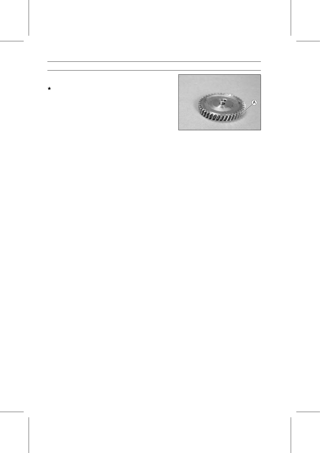
Visually inspect the oil pump drive gear teeth [A] for wear
and damage.
If the teeth are damaged or worn, replace the oil pump
drive gear.

CRANKSHAFT/CRANKCASE 9-15

Camshaft

Camshaft Removal

Remove:

Engine (see Engine Removal in the Engine Removal/In-
stallation chapter)
Cylinder Head (see Cylinder Head Removal in the En-
gine Top End chapter)
Valve Lifters (see Valve Lifter Removal in the Engine Top
End chapter)
Oil Pan (see Oil Pan and Oil Strainer Removal in the
Engine Lubrication System chapter)
Timing Gear Case Cover (see Timing Gear Case Re-
moval)

Temporarily, install the flywheel to hold the crankshaft.

Using the flywheel holder [A] angled toward the rear of
the engine, hold the crankshaft.

Special Tool - Flywheel Holder: 57001-1438

Remove:

Camshaft Drive Gear Bolt [A]
Camshaft Drive Gear [B]

Mark the positions [A] of the camshaft drive gear [B] and
idle gear [C] so that the camshaft drive gear can be in-
stalled later in the same position.

Do not turn the idle gear while the camshaft drive gear is
removed.

9-16 CRANKSHAFT/CRANKCASE

Camshaft

Remove:

Camshaft Retainer Bolts [A]
Camshaft Retainer [B]
Camshaft [C]

Use care when removing the camshaft to prevent damag-
ing the cam bearings, journals and lobes.

Camshaft Installation

Apply engine oil to all cam parts and journals.

Install the camshaft [A].

Take care when installing the camshaft to prevent dam-
aging the cam bearings, journals and lobes.

Install:

Camshaft Retainer
Camshaft Retainer Bolts

Torque - Camshaft Retainer Bolts: 7.8 N·m (0.80 kgf·m, 69

in·lb)

Install the camshaft drive gear [A].

Fit the groove [B] in the camshaft drive gear onto the key
on the camshaft.

Align the marks [C] on the camshaft drive gear and idle
gear marked when removing.

If the idle gear is turned, set the timing gears to the original
positions (see Timing Gear Case Installation).

Move the flywheel holder [A] to the forward side of the
engine to hold the crankshaft.

Special Tool - Flywheel Holder: 57001-1438

Tighten:

Torque - Camshaft Drive Gear Bolt [A]: 43 N·m (4.4 kgf·m,

32 ft·lb)

Install the removed parts (see appropriate chapters).

CRANKSHAFT/CRANKCASE 9-17

Camshaft

Camshaft Inspection

Measure the overall height [A] of each cam.
If any cam has worn past the service limit, replace the
camshaft.

Cam Height

Standard:

Inlet

30.065

∼ 30.135 mm (1.1837 ∼ 1.1864 in.)

Exhaust

30.065

∼ 30.135 mm (1.1837 ∼ 1.1864 in.)

Service Limit:

Inlet

29.965 mm (1.1797 in.)

Exhaust

29.965 mm (1.1797 in.)

Measure the diameter of the camshaft journals.
If any journals has worn past the service limit, replace the
camshaft.

Camshaft Journal Diameter

Standard:

Right Side [A]

35.959

∼ 35.975 mm

(1.4157

∼ 1.4163 in.)

Center [B]

35.910

∼ 35.955 mm

(1.4138

∼ 1.4155 in.)

Left Side [C]

35.910

∼ 35.955 mm

(1.4138

∼ 1.4155 in.)

Service Limit:

Right Side [A]

35.89 mm (1.413 in.)

Center [B]

35.84 mm (1.411 in.)

Left Side [C]

35.84 mm (1.411 in.)

Measure the camshaft runout.
If the measurement exceeds the service limit, replace the
camshaft.

Camshaft Runout

Service Limit:

0.03 mm (0.0012 in.)


Content   ..  51  52  53  54   ..