Kawasaki Diesel MULE 4010 TRANS 4x4 (KAF950G9). Manual - part 52
 

  Index      Engines     Kawasaki Diesel MULE 4010 TRANS 4x4 (KAF950G9) - service manual


Search            


Content   ..  50  51  52  53   ..


Kawasaki Diesel MULE 4010 TRANS 4x4 (KAF950G9). Manual - part 52


9-10 CRANKSHAFT/CRANKCASE

Timing Gear Case

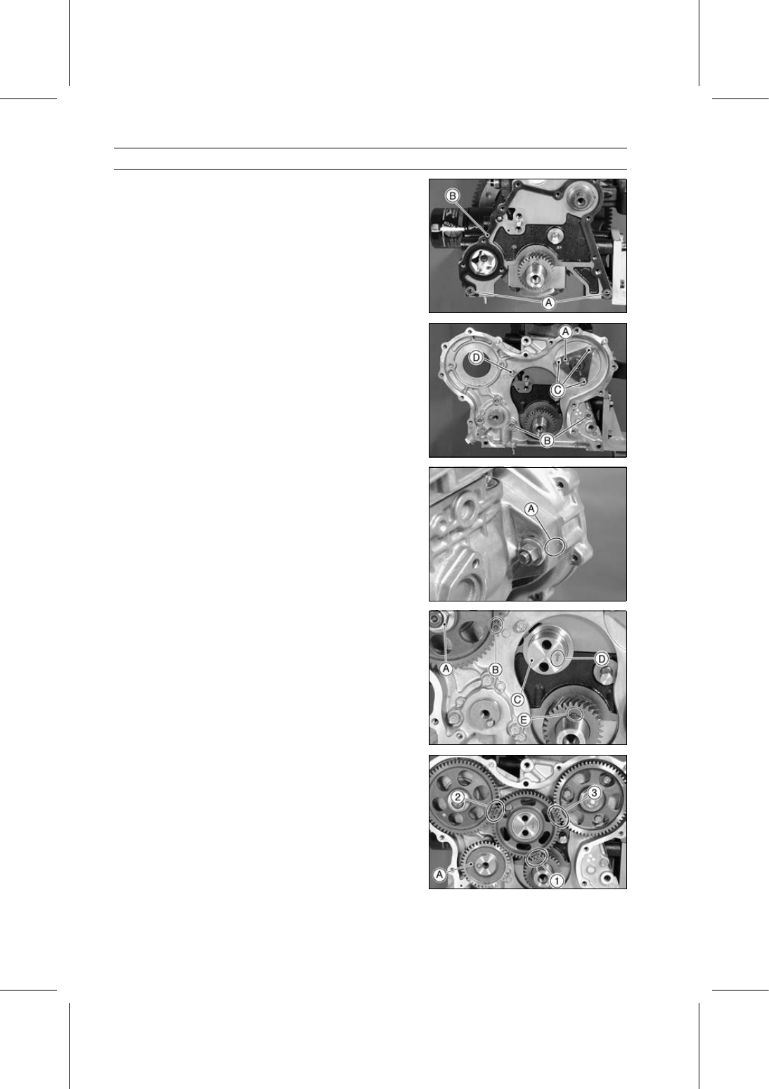
Install:

Dowel Pins [A]
New Timing Gear Case Gasket [B]
Timing Gear Case

Rotate the oil pump shaft to engage oil pump rotors.

Install the camshaft retainer [A].

Tighten:

Torque - Camshaft Retainer Bolts: 7.8 N·m (0.80 kgf·m, 69

in·lb)

Timing Gear Case Bolts: 7.8 N·m (0.80 kgf·m, 69

in·lb)

28 mm (1.10 in.) [B]
18 mm (0.71 in.) [C]
16 mm (0.63 in.) [D]

Install the fuel injection pump temporarily.

Align the marks [A] on the injection pump and the timing
gear case.

Install:

Fuel Injection Pump Drive Gear and Nut [A]
Camshaft Drive Gear and Bolt

Face the timing marks [B] on the gears upward.

Install the idle gear shaft [C] with the arrow [D] facing the
engine top.

Position the crankshaft key [E] upward (top position).

Install the idle gear so that the timing marks on the gears
are positioned as shown in the figure.

[1] Idle Gear (AA) — (A) Crankshaft Gear
[2] Idle Gear (C) — (CC) or (C) Fuel Injection Pump Drive
Gear
[3] Idle Gear (BB) — (B) Camshaft Drive Gear

Install the oil pump drive gear [A] and bolt.

CRANKSHAFT/CRANKCASE 9-11

Timing Gear Case

Temporarily install the flywheel [A] to hold the crankshaft.

Using the flywheel holder [B] angled toward the rear of
the engine, hold the crankshaft.

Special Tool - Flywheel Holder: 57001-1438

Install the thrust plate [A].

Tighten:

Torque - Idle Gear Bolts [B]: 25 N·m (2.5 kgf·m, 18 ft·lb)

Position the flywheel holder to the forward side of the en-
gine.

Tighten:

Torque - Fuel Injection Pump Drive Gear Nut [C]: 64 N·m

(6.5 kgf·m, 47 ft·lb)

Camshaft Drive Gear Bolt [D]: 43 N·m (4.4 kgf·m,

32 ft·lb)

Oil Pump Drive Gear Bolt [E]: 20 N·m (2.0 kgf·m,

15 ft·lb)

Install:

New Timing Gear Case Cover Gasket
Dowel Pins [F]

Confirm the small hole in the oil nozzle [A] faces the en-
gagement of the idle gear and camshaft drive gear.

Tighten:

Torque - Oil Nozzle: 14 N·m (1.4 kgf·m, 10 ft·lb)

Install:

Timing Gear Case Cover
Bracket [A]

Tighten:

Torque - Timing Gear Case Cover Bolts: 7.8 N·m (0.80

kgf·m, 69 in·lb)

55 mm (2.17 in.) [B]
45 mm (1.77 in.) [C]
30 mm (1.18 in.) [D]

9-12 CRANKSHAFT/CRANKCASE

Timing Gear Case

Position the flywheel holder [A] back to the rear side of
the engine as shown in the figure.

Special Tool - Flywheel Holder: 57001-1438

Wipe off the excessive oil stuck on the tapered areas of
the pulley and its engaging area with a ragged cloth be-
fore installation.

Install the crankshaft pulley [A] and bolt.

Fit the hole [B] in the crankshaft pulley on the pin [C] in
the crankshaft gear.

Apply thin coat of engine oil to the threads of tightening
bolt. Do not apply excessive oil to its threads.

Tighten:

Torque - Crankshaft Pulley Bolt: 98 N·m (10.0 kgf·m, 72.3

ft·lb)

Install the removed parts (see appropriate chapters).

Adjust the fuel injection pump timing (see Fuel Injection
Pump Timing Inspection in the Fuel System chapter)

Timing Gear Case Cover Oil Seal Replacement

Remove:

Timing Gear Case Cover (see Timing Gear Case Re-
moval)
Oil Seal [A]

Replace the oil seal with new one.

Apply grease to the new oil seal.

Press in the oil seal with the manufacturer’s marks facing
out.

Special Tool - Timing Gear Cover Oil Seal Driver [A]: 57001

-1436

CRANKSHAFT/CRANKCASE 9-13

Timing Gear Case

Timing Gear Inspection

Inspect the timing gears using the following sequence.

Check the timing gear backlash between the idle gear [A]
and crankshaft gear [B].

Remove:

Camshaft Drive Gear (see Timing Gear Case Removal)
Fuel Injection Pump Drive Gear (see Timing Gear Case
Removal)
Oil Pump Drive Gear (see Timing Gear Case Removal)

Set the tip of the dial gauge [C] on the idle gear tooth.

Hold the crankshaft.

Move the idle gear back and forth noting indicator reading.

Timing Gear Backlash

Service Limit:

0.2 mm (0.008 in.)

If the backlash exceeds the service limit, check the idle
gear bearing and shaft for wear.

Idle Gear Inside Diameter [A]

Service Limit:

34.17 mm (1.3453 in.)

Idle Gear Shaft Outside Diameter [B]

Service Limit:

33.91 mm (1.3350 in.)

If the idle gear bearing and shaft are within the service
limit, replace the idle gear and recheck the backlash.
If the backlash exceeds the service limit with a new idle
gear, crankshaft gear is worn.
If the crankshaft gear is worn, replace the crankshaft.

Check the timing gear backlash between the camshaft
drive gear [A] and idle gear [B].

Set the tip of the dial gauge [C] on the camshaft drive gear
tooth.

Hold the idle gear.

Move the camshaft drive gear back and forth noting indi-
cator reading.

Timing Gear Backlash

Service Limit:

0.2 mm (0.008 in.)

If the backlash exceeds the service limit, replace the
camshaft drive gear.

Check the timing gear backlash between the fuel injection
pump drive gear [A] and idle gear [B].

Set the tip of the dial gauge [C] on the fuel injection pump
drive gear tooth.

Hold the idle gear.

Move the fuel injection pump drive gear back and forth
noting indicator reading.

Timing Gear Backlash

Service Limit:

0.2 mm (0.008 in.)

If the backlash exceeds the service limit, replace the fuel
injection pump drive gear.


Content   ..  50  51  52  53   ..