Kawasaki Diesel MULE 4010 TRANS 4x4 (KAF950G9). Manual - part 51
 

  Index      Engines     Kawasaki Diesel MULE 4010 TRANS 4x4 (KAF950G9) - service manual


Search            


Content   ..  49  50  51  52   ..


Kawasaki Diesel MULE 4010 TRANS 4x4 (KAF950G9). Manual - part 51


9-6 CRANKSHAFT/CRANKCASE

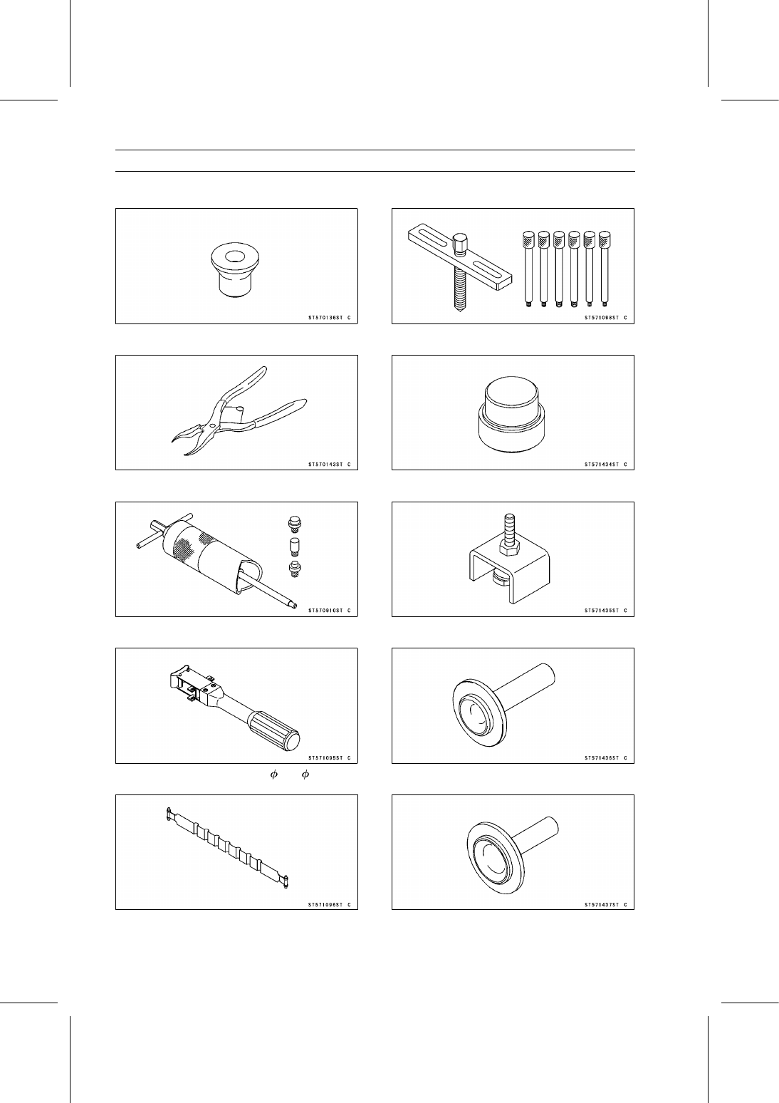
Special Tools

Bearing Puller Adapter:
57001-136

Inside Circlip Pliers:
57001-143

Piston Pin Puller Assembly:
57001-910

Piston Ring Compressor Grip:
57001-1095

Piston Ring Compressor Belt, 50

∼ 67:

57001-1096

Crankcase Splitting Tool Assembly:
57001-1098

Camshaft Bearing Driver:
57001-1434

Camshaft Bearing Remover:
57001-1435

Timing Gear Cover Oil Seal Driver:
57001-1436

Retainer Oil Seal Driver:
57001-1437

CRANKSHAFT/CRANKCASE 9-7

Special Tools

Flywheel Holder:
57001-1438

9-8 CRANKSHAFT/CRANKCASE

Timing Gear Case

Timing Gear Case Removal

Remove:

Engine (see Engine Removal in the Engine Removal/In-
stallation chapter)
Fan Belt (see Alternator Removal in the Electrical Sys-
tem chapter)

Using the flywheel holder [A], hold the crankshaft.

Special Tool - Flywheel Holder: 57001-1438

Remove the crankshaft pulley bolt [A].

Remove the crankshaft pulley [A].

Special Tools - Crankcase Splitting Tool Assembly [B]:

57001-1098

Bearing Puller Adapter [C]: 57001-136

Remove:

Oil Pan and Oil Strainer (see Oil Pan and Oil Strainer
Removal in the Engine Lubrication System chapter)
Timing Gear Case Cover Bolts [A]
Timing Gear Case Cover [B]
Bracket [C]

Temporary, install the flywheel for the crankshaft holding.

Using the flywheel holder [A], hold the crankshaft.

Special Tool - Flywheel Holder: 57001-1438

CRANKSHAFT/CRANKCASE 9-9

Timing Gear Case

Remove:

Gear Nut [A]
Gear Bolts [B]
Oil Pump Drive Gear [C]
Camshaft Drive Gear [D]

Position the flywheel holder to the opposite side.

Remove:

Idle Gear Bolts [E]
Thrust Plate [F]
Idle Gear [G]

Remove the idle gear shaft [A].

Using a suitable bearing puller [B], remove the fuel injec-
tion pump drive gear [C].

Remove the fuel injection pump [D] (see Fuel Injection
Pump Removal in the Fuel System chapter).

Remove:

Camshaft Retainer Bolts [A]
Camshaft Retainer [B]
Timing Gear Case Bolts [C]
Timing Gear Case [D]

Remove the oil pump outer rotor [A].

Timing Gear Case Installation

Clean and lubricate the oil pump outer rotor [A] with en-
gine oil.

Install the oil pump outer rotor with the punch mark [B]
facing inside.


Content   ..  49  50  51  52   ..