Kawasaki Diesel MULE 4010 TRANS 4x4 (KAF950G9). Manual - part 54
 

  Index      Engines     Kawasaki Diesel MULE 4010 TRANS 4x4 (KAF950G9) - service manual


Search            


Content   ..  52  53  54  55   ..


Kawasaki Diesel MULE 4010 TRANS 4x4 (KAF950G9). Manual - part 54


9-18 CRANKSHAFT/CRANKCASE

Crankshaft and Connecting Rods

Connecting Rod Removal

Remove:

Engine (see Engine Removal in the Engine Removal/In-
stallation chapter)
Cylinder Head (see Cylinder Head Removal in the En-
gine Top End chapter)
Valve Lifters (see Valve Lifter Removal in the Engine Top
End chapter)
Oil Pan (see Oil Pan and Oil Strainer Removal in the
Engine Lubrication System chapter)

Remove the carbon to prevent damaging the piston rings
or piston.

NOTE

Number the connecting rod/piston assemblies before
removing.

Remove:

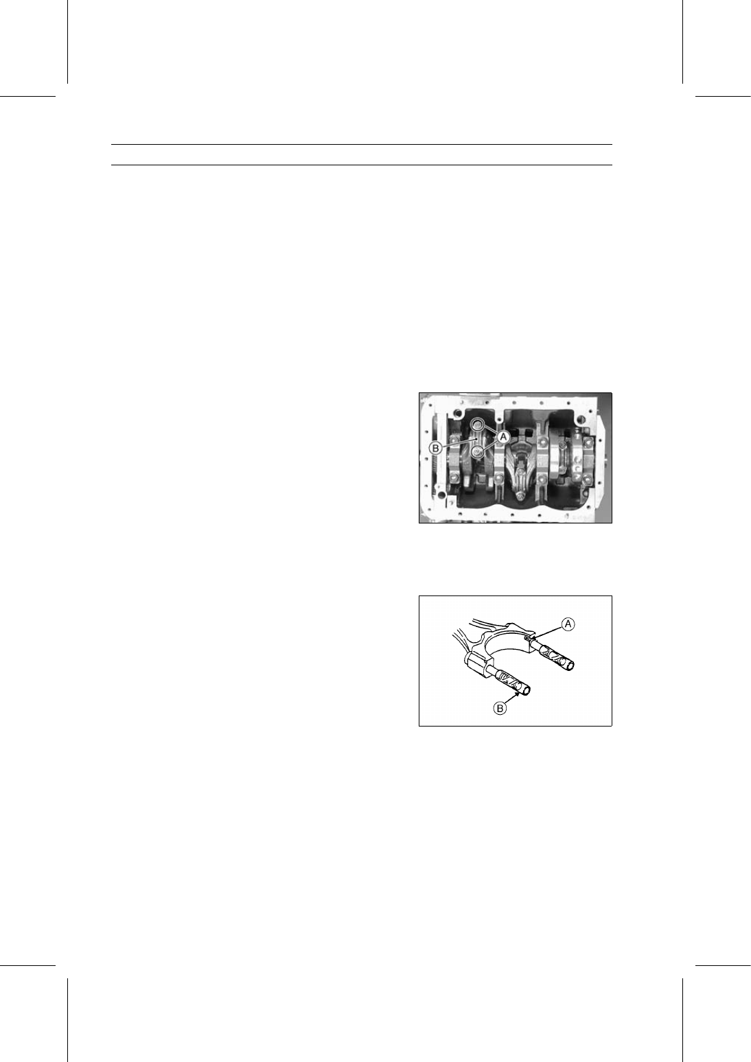
Connecting Rod Cap Nuts [A]
Connecting Rod Cap [B]

Push the connecting rod end into the cylinder, and pull the
piston and connecting rod out of the cylinder.

Reassemble the connecting rod cap to the connecting rod
to prevent interchanging components.

Connecting Rod Installation

Install the connecting rod bearing inserts.

Be sure tang [A] on the bearing inserts are seated in the
notches in the connecting rod and cap.

Install a piece of vinyl tubing [B] over each connecting
rod threads to prevent damage to the threads or crankpin
when installing the connecting rod.

Apply engine oil to the following parts.

Cylinder Bores
Pistons and Piston Rings
Bearing Inserts and Crankpins

Rotate the crankshaft so that the crankpin is at bottom of
the stroke.

CRANKSHAFT/CRANKCASE 9-19

Crankshaft and Connecting Rods

Insert the piston and connecting rod with the arrow [A] on
the piston facing right side (timing gears side).

Using the piston ring compressor grip [B] and the belt [C],
lightly tap the top of the piston with a plastic mallet to insert
the piston and connecting rod into the cylinder.

Special Tools - Piston Ring Compressor Grip: 57001-1095

Piston Ring Compressor Belt,

50

∼ 67:

57001-1096

Apply engine oil to the threads of the connecting rod bolt.

Install the connecting rod caps with ID mark [A] facing
right side (timing gears side).

Tighten:

Torque - Connecting Rod Cap Nuts: 36 N·m (3.7 kgf·m, 27

ft·lb)

After tightening the cap nuts, make sure the crankshaft
rotates freely.

Crankshaft Removal

Remove:

Camshaft (see Camshaft Removal)
Timing Gear Case (see Timing Gear Case Removal)
Connecting Rods (see Connecting Rod Removal)
Oil Seal Retainer Bolts [A]
Oil Seal Retainer [B] and Gasket

Remove:

Crankshaft Main Bearing Cap Bolts [A]
Crankshaft Main Bearing Caps [B]
Crankshaft [C]
Thrust Washers (#3 Main Bearing)

Remove the upper main bearing inserts from saddles and
place with the respective bearing caps.

Crankshaft Installation

Install the upper main bearing inserts in the crankcase.

NOTE

Upper main bearing inserts have an oil groove [A] and
oil hole [B].

Be sure the bearing inserts are seated in the saddles,
and the tangs in the bearing inserts are aligned with the
notches in the saddles.

9-20 CRANKSHAFT/CRANKCASE

Crankshaft and Connecting Rods

Install the lower main bearing inserts [A] in the bearing
caps [B].

Be sure the bearing inserts are seated in the bearing
caps, and the tangs [C] in the bearing inserts are aligned
with the notches [D] in the bearing caps.

Apply engine oil to the main bearing inserts.

Install the thrust washers [A] at #3 main bearing with
grooves [B] facing out.

Install the crankshaft with the gear facing the right side
(timing gears side).

Take care not to damage the journals or bearing inserts.

Apply engine oil to the crankshaft main journals.

Install the main bearing caps in their respective positions
with the arrows [A] facing the right side (timing gear side).

Tighten the cap bolts following the tightening sequence [1

∼ 4].

Torque - Crankshaft Main Bearing Cap Bolts: 59 N·m (6.0

kgf·m, 44 ft·lb)

After tightening the cap bolts, make sure the crankshaft
rotates freely.

Install:

New Oil Seal Retainer Gasket [A]
Dowel Pins [B]
Oil Seal Retainer

Tighten:

Torque - Oil Seal Retainer Bolts: 5.4 N·m (0.55 kgf·m, 48

in·lb)

Connecting Rod Big End Side Clearance

Measure connecting rod big end side clearance.

Insert a thickness gauge between the connecting rod big
end [A] and either crank web [B] to determine clearance.
If the clearance exceeds the service limit, replace the con-
necting rod with a new one and then check clearance
again. If the clearance is too large after connecting rod
replacement, the crankshaft also must be replaced.

Connecting Rod Big End Side Clearance

Standard:

0.15

∼ 0.28 mm (0.0059 ∼ 0.0110 in.)

Service Limit:

0.3 mm (0.0118 in.)

CRANKSHAFT/CRANKCASE 9-21

Crankshaft and Connecting Rods

Connecting Rod Inspection

Measure the inside diameter [A] of the connecting rod
small end.
If the connecting rod small end bore has worn past the
service limit, replace the connecting rod.

Connecting Rod Small End

Service Limit

Inside Diameter:

18.03 mm (0.7098 in.)

Measure the inside diameter [A] of the connecting rod big
end.

With bearings removed, install the connecting rod cap.

Tighten:

Torque - Connecting Rod Cap Nuts: 36 N·m (3.7 kgf·m, 27

ft·lb)

If the connecting rod big end out of round exceeds the
service limit, replace the connecting rod.

Connecting Rod Big End

Service Limit

Out of Round:

0.02 mm (0.0008 in.)

Check for a bent or twisted connecting rod.

NOTE

The thrust faces must be free of any burrs or nicks, or
the connecting rod will not lay flat on a surface plate.

Put the connecting rod on a surface plate. Any distortion
will be evident by a rocking motion.
If a 0.05 mm (0.0020 in.) thickness gauge can be inserted
at the connecting rod small end, replace the connecting
rod.

Connecting Rod Thrust Faces

Service Limit

Distortion:

0.05 mm (0.0020 in.)

Crankshaft Inspection

Visually inspect the crankshaft main journals and
crankpins for grooves or signs of scoring.
If any damage is found, the crankshaft must be re-ground
or replaced.


Content   ..  52  53  54  55   ..