Kawasaki Diesel MULE 4010 TRANS 4x4 (KAF950G9). Manual - part 46
 

  Index      Engines     Kawasaki Diesel MULE 4010 TRANS 4x4 (KAF950G9) - service manual


Search            


Content   ..  44  45  46  47   ..


Kawasaki Diesel MULE 4010 TRANS 4x4 (KAF950G9). Manual - part 46


7-8 ENGINE LUBRICATION SYSTEM

Engine Oil and Oil Filter

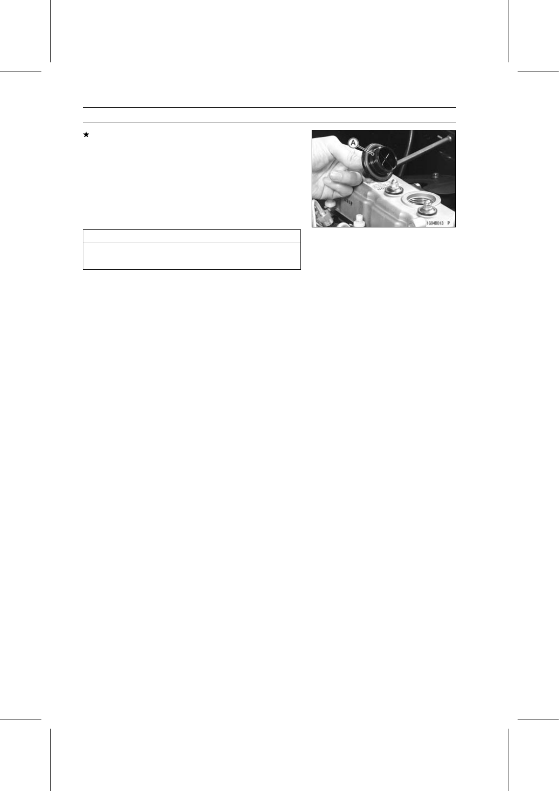
If the oil level is too low, add the correct amount of oil
through the oil filler opening. Use the same type and
make of oil that is already in the engine.

Oil Filler Cap [A]

NOTE

If the engine oil type and make are unknown, use any
brand of the specified oil to top up the level in preference
to running the engine with the oil level low. Then at your
earliest convenience, change the oil completely.

NOTICE

To avoid the engine damage, do not fill the engine
oil above the full level.

Engine Oil and/or Oil Filter Change

Refer to the Engine Oil and/or Oil Filter Change in the
Periodic Maintenance chapter.

Oil Filter Removal

Refer to the Oil Filter Removal in the Periodic Mainte-
nance chapter.

Oil Filter Installation

Refer to the Oil Filter Installation in the Periodic Mainte-
nance chapter.

ENGINE LUBRICATION SYSTEM 7-9

Oil Pan and Oil Strainer

Oil Pan and Oil Strainer Removal

Remove:

Engine (see Engine Removal in the Engine Removal/In-
stallation chapter)
Flywheel and End Plate (see End Plate Removal in the
Crankshaft/Crankcase chapter)
Oil Pan Bolts [A] and Nuts [B]

Remove the oil pan [C] straight so that the baffle plate in
the oil pan does not to hitch the oil strainer.

Remove:

Oil Strainer Mounting Bolt [A] and Nuts [B]
Oil Strainer [C]

Oil Pan and Oil Strainer Installation

Clean the oil pan and oil strainer thoroughly whenever
they are removed.

Replace the oil strainer gasket [A] with a new one.

Tighten:

Torque - Oil Strainer Mounting Bolt and Nuts: 7.8 N·m (0.80

kgf·m, 69 in·lb)

Apply liquid gasket [A] to the mating surface as shown in
the figure.

Sealant - Three Bond: 1207F

Install the oil pan [B] so that the baffle plate [C] does not
hitch the oil strainer.

Tighten:

Torque - Oil Pan Bolts and Nuts: 7.8 N·m (0.80 kgf·m, 69

in·lb)

Oil Strainer Cleaning/Inspection

Clean the oil strainer, and remove any particles stuck to
it.

NOTE

While cleaning the strainer, check for any metal parti-
cles that might indicate internal engine damage.

Check the screen [A] carefully for any damage: holes and
broken wire.
If the screen is damaged, replace the oil strainer.

7-10 ENGINE LUBRICATION SYSTEM

Oil Pump

Oil Pump Removal

Remove:

Timing Gear Case (see Timing Gear Case Removal in
the Crankshaft/Crankcase chapter)
Oil Pump Outer Rotor [A]

Oil Pump Installation

Clean and lubricate the oil pump outer rotor [A] with en-
gine oil.

Apply engine oil to the oil pump outer rotor.

Install the oil pump outer rotor with the punch mark [B]
facing inside.

Install the timing gear case (see Timing Gear Case Instal-
lation in the Crankshaft/Crankcase chapter).

Oil Pump Inspection

Remove the timing gear case cover (see Timing Gear
Case Removal in the Crankshaft/Crankcase chapter).

Set up a dial gauge [A] against the oil pump gear [B] as
shown in the figure and measure the oil pump side clear-
ance.

Oil Pump Side Clearance

Standard:

0.030

∼ 0.096 mm (0.0012 ∼ 0.0038 in.)

Service Limit:

0.15 mm (0.0059 in.)

If the clearance exceeds the service limit, go to next pro-
cedure.

Remove the oil pump outer rotor (see Oil Pump Removal).

Measure the depth of the pump housing in the crankcase
[A] with a depth micrometer [B] at several points.

Oil Pump Housing Depth

Standard:

12.63

∼ 12.67 mm (0.4972 ∼ 0.4988 in.)

Service Limit:

12.72 mm (0.5008 in.)

If the depth exceeds the service limit, replace the
crankcase.
If the depth within the service limit, replace the timing gear
case.

Visually inspect the oil pump inner rotor [A] and outer rotor
[B].
If there is any damage or uneven wear, replace the timing
gear case [C].

ENGINE LUBRICATION SYSTEM 7-11

Relief Valve

Relief Valve Removal

Drain the engine oil (see Engine Oil and/or Oil Filter
Change in the Periodic Maintenance chapter).

Remove:

Relief Valve Bolt [A] and Washer
Relief Valve Spring
Relief Valve Plunger

Relief Valve Installation

Install:

Relief Valve Plunger [A]
Relief Valve Spring [B]
Washer [C] and Relief Valve Bolt [D]

Tighten:

Torque - Relief Valve Bolt: 39 N·m (4.0 kgf·m, 29 ft·lb)

Relief Valve Inspection

Visually inspect the relief valve spring [A] and plunger [B].
If any nicks or burrs are found during the above inspec-
tion, replace the parts.

Measure the relief valve spring free length.
If the spring is shorter than the standard, replace the
spring.

Relief Valve Spring Free Length

Standard:

34.5

∼ 36.5 mm (1.358 ∼ 1.437 in.)


Content   ..  44  45  46  47   ..