Kawasaki Diesel MULE 4010 TRANS 4x4 (KAF950G9). Manual - part 44
 

  Index      Engines     Kawasaki Diesel MULE 4010 TRANS 4x4 (KAF950G9) - service manual


Search            


Content   ..  42  43  44  45   ..


Kawasaki Diesel MULE 4010 TRANS 4x4 (KAF950G9). Manual - part 44


6-28 CONVERTER SYSTEM

Driven Pulley

Driven Pulley Installation

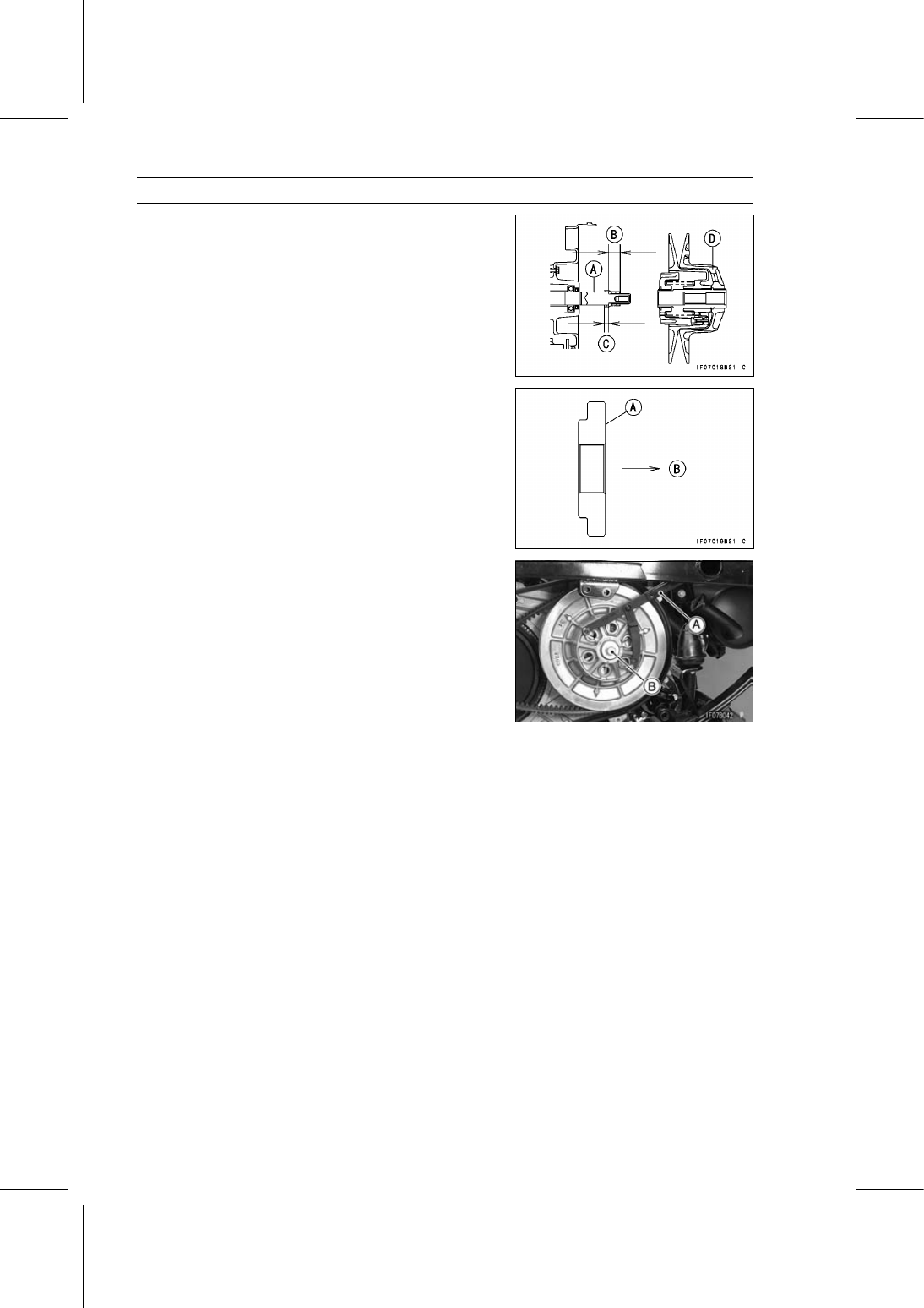
Clean the transmission driven shaft [A], and apply molyb-
denum disulfide grease width the specified range on it.

20

∼ 25 mm (0.79 ∼ 0.98 in.) [B]

5

∼ 10 mm (0.20 ∼ 0.39 in.) [C]

Apply molybdenum disulfide grease thinly in the area [C].

Install the driven pulley [D].

Install the stepped collar [A] on the pulley as shown in the
figure.

Bolt Head [B]

Apply a non-permanent locking agent to the threads of
the driven pulley bolt.

Using a flywheel & pulley holder [A], tighten the driven
pulley bolt [B].

Special Tool - Flywheel & Pulley Holder: 57001-1605

Torque - Driven Pulley Bolt: 93 N·m (9.5 kgf·m, 69 ft·lb)

Install the removed parts (see appropriate chapters).

ENGINE LUBRICATION SYSTEM 7-1

7

Engine Lubrication System

Table of Contents

Exploded View........................................................................................................................

7-2

Specifications .........................................................................................................................

7-4

Special Tools and Sealant ......................................................................................................

7-5

Engine Oil Flow Chart.............................................................................................................

7-6

Engine Oil and Oil Filter..........................................................................................................

7-7

Oil Level Inspection...........................................................................................................

7-7

Engine Oil and/or Oil Filter Change ..................................................................................

7-8

Oil Filter Removal .............................................................................................................

7-8

Oil Filter Installation ..........................................................................................................

7-8

Oil Pan and Oil Strainer..........................................................................................................

7-9

Oil Pan and Oil Strainer Removal .....................................................................................

7-9

Oil Pan and Oil Strainer Installation ..................................................................................

7-9

Oil Strainer Cleaning/Inspection .......................................................................................

7-9

Oil Pump.................................................................................................................................

7-10

Oil Pump Removal ............................................................................................................

7-10

Oil Pump Installation .........................................................................................................

7-10

Oil Pump Inspection..........................................................................................................

7-10

Relief Valve.............................................................................................................................

7-11

Relief Valve Removal........................................................................................................

7-11

Relief Valve Installation.....................................................................................................

7-11

Relief Valve Inspection......................................................................................................

7-11

Oil Pressure Measurement.....................................................................................................

7-12

Oil Pressure Measurement ...............................................................................................

7-12

Oil Pressure Switch ................................................................................................................

7-13

Oil Pressure Switch Removal ...........................................................................................

7-13

Oil Pressure Switch Installation ........................................................................................

7-13

Oil Nozzle ...............................................................................................................................

7-14

Oil Nozzle Installation .......................................................................................................

7-14

7-2 ENGINE LUBRICATION SYSTEM

Exploded View

ENGINE LUBRICATION SYSTEM 7-3

Exploded View

Torque

No.

Fastener

N·m

kgf·m

ft·lb

Remarks

1

Engine Oil Drain Plugs

34

3.5

25

2

Oil Filter Stud Bolt

44

4.5

32

3

Oil Nozzle

14

1.4

10

4

Oil Pan Bolts and Nuts

7.8

0.80

69 in·lb

5

Oil Pressure Switch

14

1.4

10

SS

6

Oil Pump Drive Gear Bolt

20

2.0

15

7

Oil Strainer Mounting Bolt and Nuts

7.8

0.80

69 in·lb

8

Relief Valve Bolt

39

4.0

29

EO: Apply engine oil.

G: Apply grease.

LG: Apply liquid gasket.

R: Replacement Parts

SS: Apply silicone sealant.


Content   ..  42  43  44  45   ..