Kawasaki Diesel MULE 4010 TRANS 4x4 (KAF950G9). Manual - part 42
 

  Index      Engines     Kawasaki Diesel MULE 4010 TRANS 4x4 (KAF950G9) - service manual


Search            


Content   ..  40  41  42  43   ..


Kawasaki Diesel MULE 4010 TRANS 4x4 (KAF950G9). Manual - part 42


6-20 CONVERTER SYSTEM

Drive Pulley

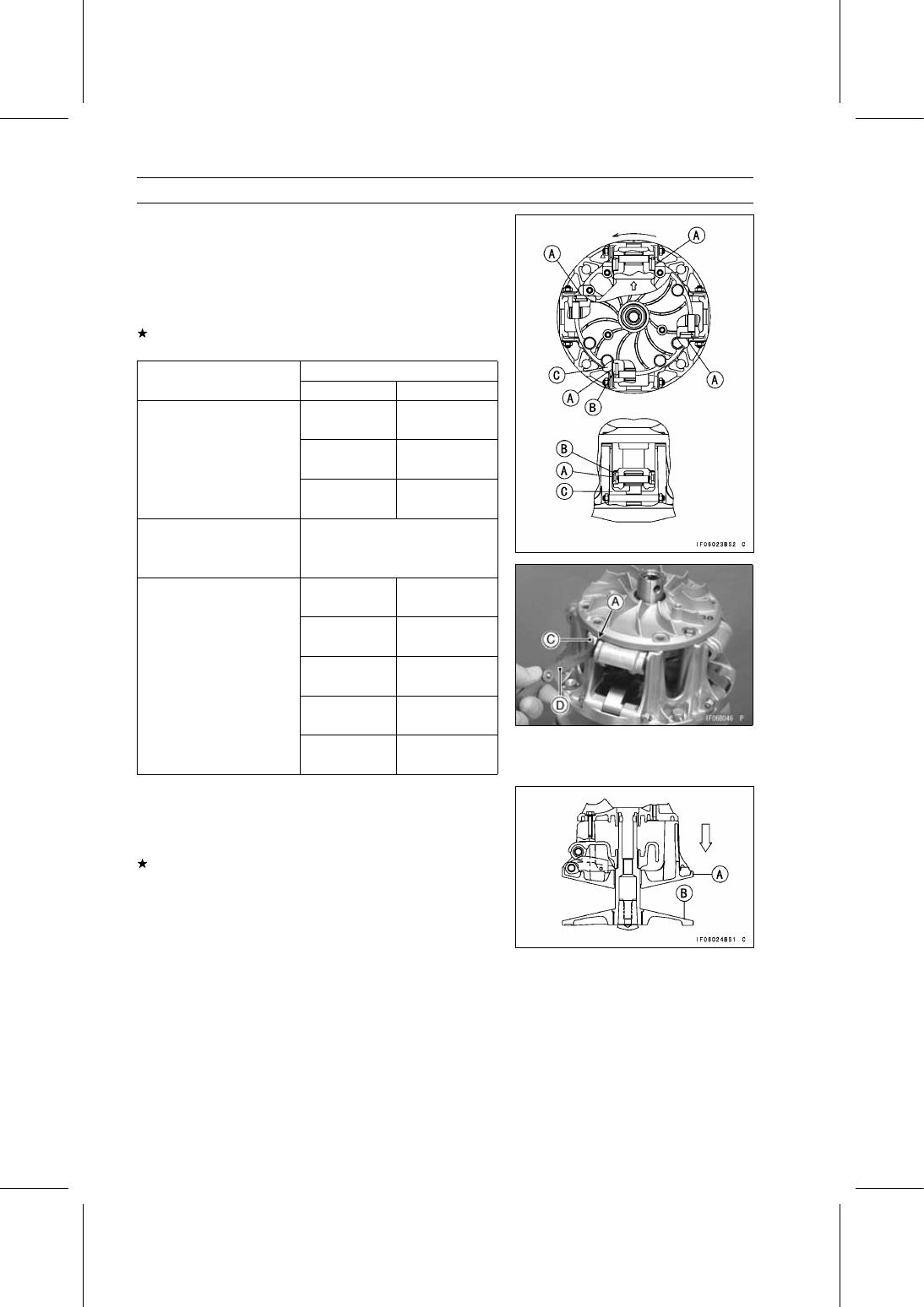
Turn the spider counterclockwise.

Measure the resulting clearance [A] between the shoe [B]
and the post [C] on the movable sheave at four posts,
using a thickness gauge [D].

Shoe Side Clearance

Standard: 0.05

∼ 0.20 mm (0.0020 ∼ 0.0079 in.)

If the clearance is not within the specified range, adjust it
according to following chart.

Present Shoes

Clearance Measurement

Part Number

Thickness

7.2 mm

49048-1087

(0.283 in.)

7.3 mm

49048-1088

(0.287 in.)

7.4 mm

up to 0.05 mm (0.0020 in.)

49048-1089

(0.291 in.)

over 0.05 to 0.20 mm

no change

(over 0.0020 to 0.0079 in.)

(49048-1090)

(7.5 mm)

(standard clearance)

(0.295 in.)

7.6 mm

49048-1091

(0.299 in.)

7.7 mm

49048-1092

(0.303 in.)

7.8 mm

49048-1093

(0.307 in.)

7.9 mm

49048-1094

(0.311 in.)

8.0 mm

over 0.20 mm (0.0079 in.)

49048-1095

(0.315 in.)

Check that the movable sheave [A] moves smoothly, after
the shoe side clearance adjustment.

The movable sheave must move freely towards the fixed
sheave [B].
If the movable sheave does not move smoothly, readjust
the shoe side clearance.

CONVERTER SYSTEM 6-21

Drive Pulley

Drive Pulley Assembly

Replace the ramp weight nuts [B] with new ones.

Install the ramp weight [A] as shown in the figure.

Tighten:

Torque - Ramp Weight Nuts: 6.9 N·m (0.70 kgf·m, 61 in·lb)

Check that the ramp weights swing smoothly.

Hold the fixed sheave [A] with the drive pulley holders [B]
in a vise.

Special Tools - Drive & Driven Pulley Holder: 57001-1412

Drive & Driven Pulley Holder: 57001-1473

Clean the threads of the fixed sheave and spider.

Install:

Movable Sheave
Spider [A] and Shoes [B]

Align the arrow [C] on the spider with the arrow [D] on the
movable sheave.

Insert the shoes so that the rubber side faces inward.

Put the drive pulley wrench [A] on the spider [B] and
tighten the bolt [C].

Special Tool - Drive Pulley Wrench: 57001-1549

Turn the wrench for tightening.

Torque - Spider: 275 N·m (28.0 kgf·m, 203 ft·lb)

Put the spring [A] in the groove of the spider.

Align the arrows [B] on the drive pulley cover and spider.

Install:

Dowel Pins [C]
Drive Pulley Cover [D]

Tighten:

Torque - Drive Pulley Cover Bolts: 13 N·m (1.3 kgf·m, 115

in·lb)

Clean the surface of the sheaves with an oil-less cleaning
fluid.

6-22 CONVERTER SYSTEM

Drive Pulley

Bushing Installation

Press the cover bushing [A] into the cover [B] using the
special tool so that the end of bushing is flush with the
shoulder [C] in the hole.

Special Tool - Bearing Driver Set: 57001-1129

Press the sheave bushing [A] into the movable sheave [B]
using the special tool so that the end of bushing is flush
with the shoulder [C] in the hole.

Special Tool - Bearing Driver Set: 57001-1129

Drive Pulley Installation

Clean the following portions with an oil-less cleaning fluid
such as trichloroethylene or acetone, and wipe off any oil
with a clean cloth from the tapers.

Fixed Sheave Tapered Portion [A]
Crankshaft Tapered Portion [B]

WARNING

These cleaning fluids are usually highly flammable
and harmful if breathed for prolonged periods. Be
sure to heed the fluid manufacturer’s warnings.

Install the drive pulley, and screw in the drive pulley bolt
with the stepped collar [A] and washers [B] as shown in
the figure.

Bolt Head [C]

Hold the drive pulley with the drive pulley holder [A].

Special Tool - Drive Pulley Holder: 57001-1548

Tighten:

Torque - Drive Pulley Bolt [B]: 93 N·m (9.5 kgf·m, 69 ft·lb)

CONVERTER SYSTEM 6-23

Drive Pulley

Press the ramp weight bushing [B] from the arrow side [A]
into the ramp weight [C] using the special tool so that the
end of bushing is flush with the shoulder [D] in the hole.

Special Tool - Bearing Driver Set: 57001-1129

Install the fan cover.

Torque - Fan Cover Bolts: 8.8 N·m (0.90 kgf·m, 78 in·lb)

Install the torque converter outer cover (see Torque Con-
verter Outer Cover Installation).


Content   ..  40  41  42  43   ..