Kawasaki Diesel MULE 4010 TRANS 4x4 (KAF950G9). Manual - part 41
 

  Index      Engines     Kawasaki Diesel MULE 4010 TRANS 4x4 (KAF950G9) - service manual


Search            


Content   ..  39  40  41  42   ..


Kawasaki Diesel MULE 4010 TRANS 4x4 (KAF950G9). Manual - part 41


6-16 CONVERTER SYSTEM

Drive Pulley

Drive Pulley Removal

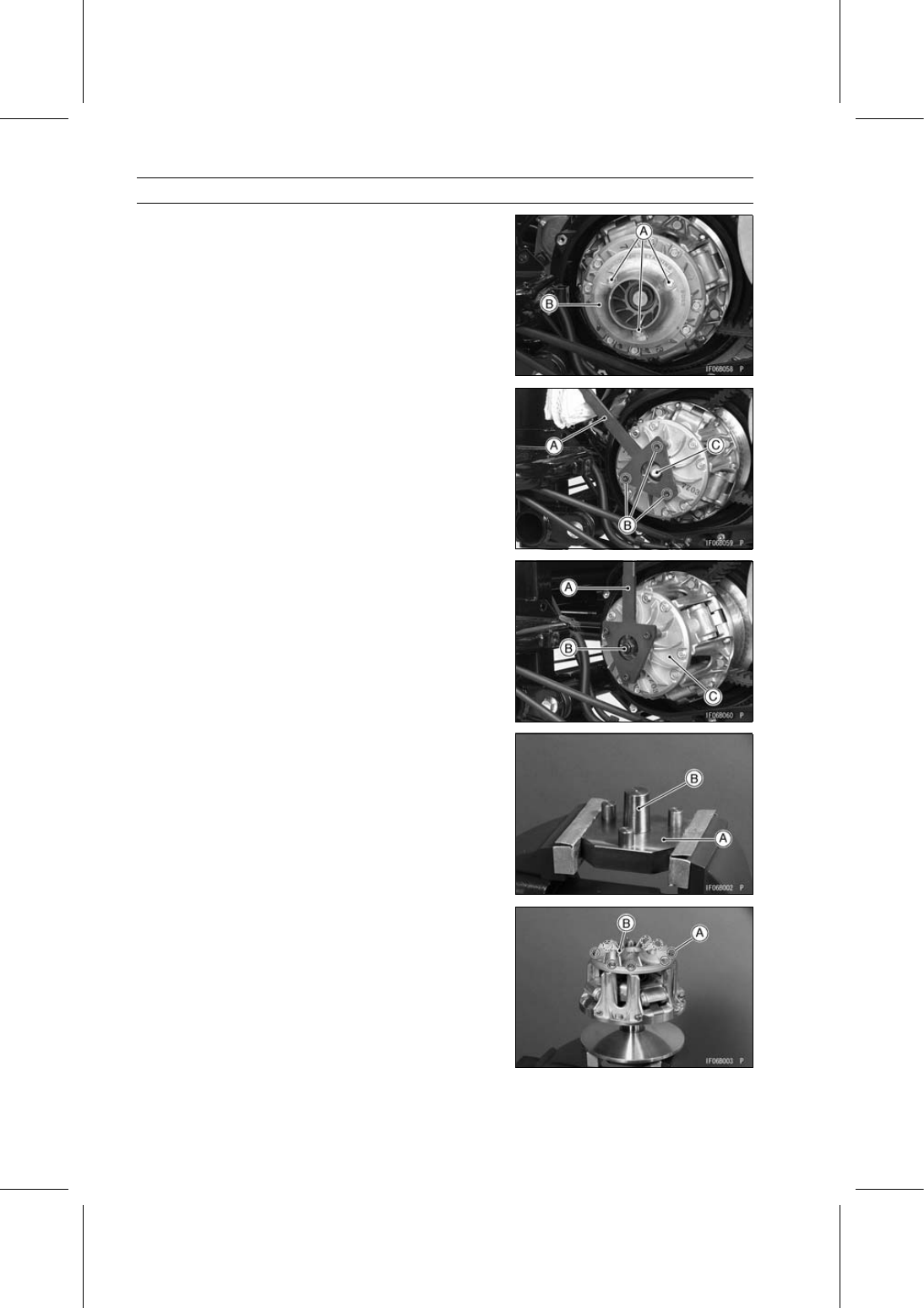
Remove:

Torque Converter Outer Cover (see Torque Converter
Outer Cover Removal)
Fan Cover Bolts [A]
Fan Cover [B]

Install the drive pulley holder [A] and tighten it with the
three Allen bolts [B] as shown in the figure.

Special Tool - Drive Pulley Holder: 57001-1548

Remove the drive pulley bolt [C] and washers.

Using the drive pulley holder [A] and drive pulley puller
bolt [B], remove the drive pulley [C] from the crankshaft.

Special Tools - Drive Pulley Puller Bolt: 57001-1429

Drive Pulley Holder: 57001-1548

Drive Pulley Disassembly

Hold the drive pulley holder [A] and drive & driven pulley
holder [B] in a vise.

Special Tools - Drive & Driven Pulley Holder: 57001-1412

Drive & Driven Pulley Holder: 57001-1473

Set the pulley onto the pulley holder.

Remove:

Drive Pulley Cover Bolts [A]
Drive Pulley Cover [B]

CONVERTER SYSTEM 6-17

Drive Pulley

Remove the spring [A].

Put the drive pulley wrench [A] on the spider [B] and
tighten the bolt [C].

Special Tool - Drive Pulley Wrench: 57001-1549

Remove the spider with the movable sheave.

Remove:

Spider [A]
Shoes [B]
Nuts [C]
Ramp Weight Pin [D]
Ramp Weight [E]
Movable Sheave [F]
Fixed Sheave [G]

Drive Pulley Inspection

If the sheave surfaces [A] appear damaged, replace the
sheaves.

6-18 CONVERTER SYSTEM

Drive Pulley

Replace any sheave which has uneven wear on the belt
contacting surface.

Sheave Surfaces [A]
Straight Edge [B]

If the cover bushing is damaged or worn, replace the drive
pulley cover.

Cover Bushing Inside Diameter [A]

Standard:

27.655

∼ 27.955 mm (1.089 ∼ 1.101 in.)

Service Limit: 27.99 mm (1.102 in.)

If the sheave bushing is damaged or worn, replace it.

Sheave Bushing Inside Diameter [A]

Standard:

38.055

∼ 38.155 mm (1.498 ∼ 1.502 in.)

Service Limit: 38.19 mm (1.504 in.)

If the spider shoes [A] are damaged, replace them.

Check the spider shoe side clearance (see Spider Shoe
Side Clearance Adjustment).

If the ramp weights [A] are damaged or worn, replace
them.
If the pins [B] are damaged, replace them.

CONVERTER SYSTEM 6-19

Drive Pulley

If the ramp weights are damaged or worn, replace them.

Rump Weight Bushing Inside Diameter [A]

Standard:

7.000

∼ 7.091 mm (0.276 ∼ 0.280 in.)

Service Limit: 7.23 mm (0.28 in.)

If the rollers [A] are damaged or worn, replace the spider
[B].
If the washers [C] are damaged or worn, replace the spi-
der.

If the spring is damaged, replace the spring.

Spring Free Length [A]

Standard:

77 mm (3.03 in.)

Spider Shoe Side Clearance Adjustment

Remove:

Drive Pulley (see Drive Pulley Removal)
Drive Pulley Cover and Spring (see Drive Pulley Disas-
sembly)

Set the drive pulley [A] without the spring onto the pulley
holders.

Special Tools - Drive & Driven Pulley Holder: 57001-1412

Drive & Driven Pulley Holder: 57001-1473

Install the following parts temporarily.

Dowel Pins
Drive Pulley Cover [B]
Two Bolts [C] (at Dowel Pins)


Content   ..  39  40  41  42   ..