Kawasaki Diesel MULE 4010 TRANS 4x4 (KAF950G9). Manual - part 40
 

  Index      Engines     Kawasaki Diesel MULE 4010 TRANS 4x4 (KAF950G9) - service manual


Search            


Content   ..  38  39  40  41   ..


Kawasaki Diesel MULE 4010 TRANS 4x4 (KAF950G9). Manual - part 40


6-12 CONVERTER SYSTEM

Torque Converter

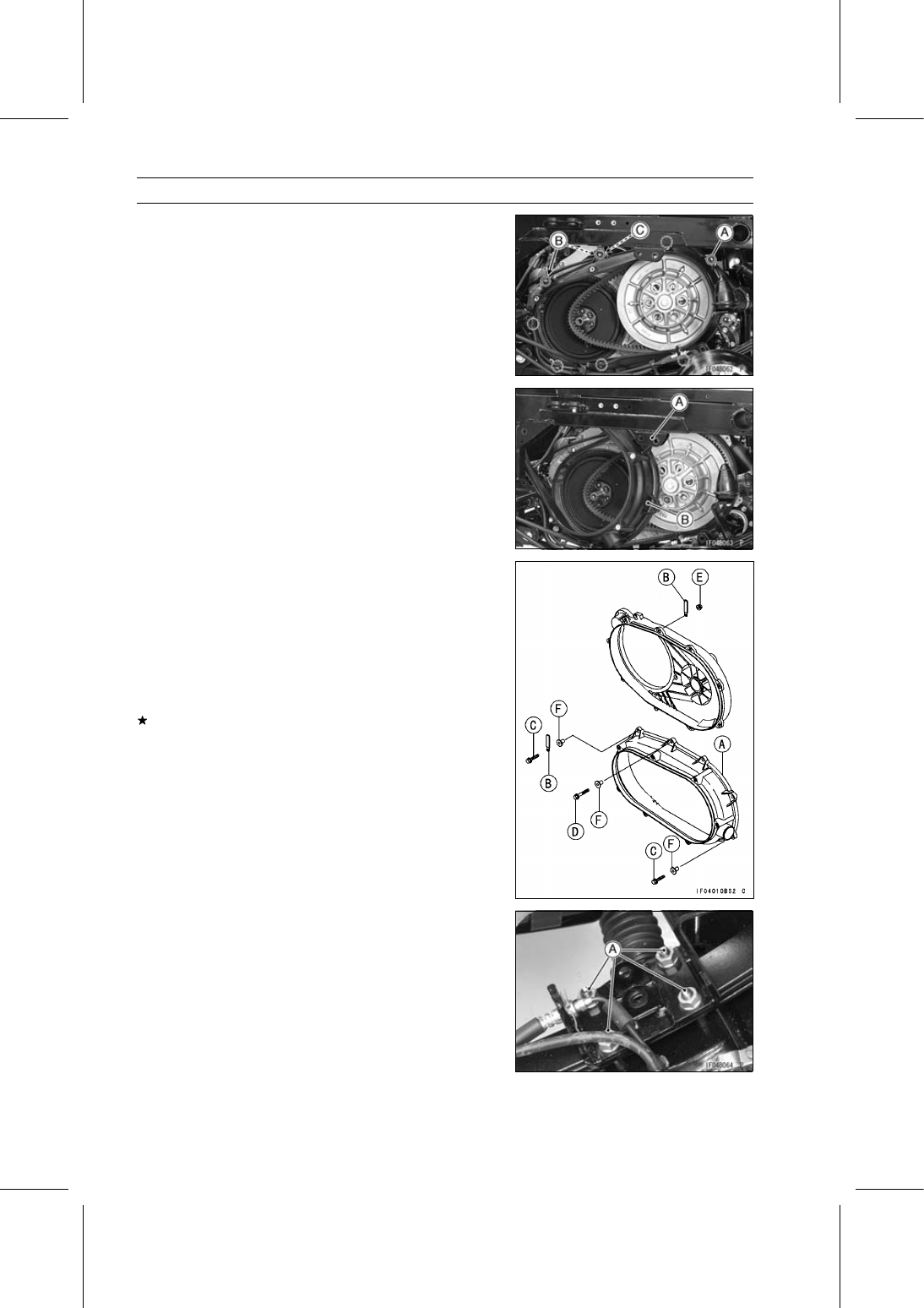
Remove:

Inner Cover Bolts [A] and Collars
Clamps [B]
Nut [C]

Avoid the bracket [A] and remove the inner cover [B] up-
ward.

Torque Converter Inner Cover Installation

Replace the nut [E] with a new one.

Install:

Inner Cover [A]
Clamps [B]
Inner Cover Bolts (L = 30 mm (1.18 in.)) [C]
Inner Cover Bolt (L = 35 mm (1.38 in.)) [D]
Nut
Collars [F]

When installing the trim, add the glue to the place be-
tween bolt hole and bolt hole.

Tighten:

Torque - Inner Cover Bolts: 4.4 N·m (0.45 kgf·m, 39 in·lb)

Inner Cover Nut: 8.8 N·m (0.90 kgf·m, 78 in·lb)

Install the drive pulley (see Drive Pulley Installation).

Install the removed parts (see appropriate chapters).

Torque Converter Case Removal

Remove:

Drive Pulley (see Drive Pulley Removal)
Driven Pulley (see Driven Pulley Removal)
Damper Bracket Nuts [A] (Loosen)

CONVERTER SYSTEM 6-13

Torque Converter

Hold the left part of the rear axle bracket with a jack [A].

Remove:

Leaf Spring Mounting Nuts [B]
Leaf Spring Rods [C]

Loosen the clamp [A] and remove the air duct [B] from the
torque converter case.

Remove:

Converter Case Bolts [A]
Converter Case Nut [B] and Washer
Torque Converter Case [C]

Place an oil pan beneath the drive shaft of the transmis-
sion case.

Avoid the brake hose bracket [A] and remove the torque
converter case [B] while pushing down the leaf spring rear
end.

Torque Converter Case Installation

Be sure to install the following on the drive shaft and trans-
mission case.

Collar [A]
O-ring [B]

Confirm the engine and transmission case position (see
Engine Installation in the Engine Removal/Installation
chapter).

6-14 CONVERTER SYSTEM

Torque Converter

Replace the nut [B] with a new one.

Install:

Torque Converter Case [A]
Nut and Washer [C]

Apply a non-permanent locking agent to the following
bolts and install them.

Converter Case Bolts (L = 55 mm (2.17 in.)) [D]
Converter Case Bolts (L = 28 mm (1.10 in.)) [E]

Tighten:

Torque - Converter Case Bolts (L = 55 mm): 27 N·m (2.8

kgf·m, 20 ft·lb)

Converter Case Bolts (L = 28 mm): 20 N·m (2.0

kgf·m, 15 ft·lb)

Tighten the damper bracket nuts in the order as shown in
the figure.

Front [A]
Outside [B]

Torque - Damper Bracket Nuts:

First: 20 N·m (2.0 kgf·m, 15 ft·lb)
Second: 44 N·m (4.5 kgf·m, 32 ft·lb)
Final: 59 N·m (6.0 kgf·m, 44 ft·lb)

Install the removed parts (see appropriate chapters).

Torque Converter Case Disassembly

Remove:

Torque Converter Case [A] (see Torque Converter Case
Removal)
Oil Seal [B]
Ball Bearing [C]
Trims [D] (if necessary)

Torque Converter Case Assembly

Apply transmission oil to the ball bearing.

Press the ball bearing [A] until it is bottomed.

Special Tool - Bearing Driver Set: 57001-1129

Apply grease to the oil seal lip.

Press the oil seal [B] in the case so that the oil seal surface
is flush [C] with the case end.
When installing the trim, add the glue to the place be-
tween bolt hole and bolt hole.

CONVERTER SYSTEM 6-15

Drive Belt

Drive Belt Removal

Remove:

Drive Pulley (see Drive Pulley Removal)
Torque Converter Inner Cover (see Torque Converter In-
ner Cover Removal)

NOTE

Before removing the drive belt, observe the direction
of the belt’s printed information [A] (such as manufac-
turer’s name and arrow marks) is facing so that it may
be reinstalled on the pulleys to rotate in the same direc-
tion as originally installed.

Remove the drive belt [B].

Drive Belt Installation

NOTE

Be sure the printed information faces the same direc-
tion so the belt rotates in the same direction as origi-
nally installed. When installing a new belt, install it so
the printed information [A] can be read from beside the
vehicle.

Installation is basically the reverse of removal.

Loop the belt over the driven pulley.

Install:

Torque Converter Inner Cover (see Torque Converter In-
ner Cover Installation)
Drive Pulley (see Drive Pulley Installation)

Put the transmission in neutral, and rotate the driven pul-
ley to allow the belt to return to the top [A] of the sheaves,
before measuring belt deflection.

Drive Belt Inspection

Refer to the Drive Belt Inspection in the Periodic Mainte-
nance chapter.

Drive Belt Deflection Inspection

Refer to the Drive Belt Deflection Inspection in the Peri-
odic Maintenance chapter.

Drive Belt Deflection Adjustment

Refer to the Drive Belt Deflection Adjustment in the Peri-
odic Maintenance chapter.


Content   ..  38  39  40  41   ..