Kawasaki Diesel MULE 4010 TRANS 4x4 (KAF950G9). Manual - part 43
 

  Index      Engines     Kawasaki Diesel MULE 4010 TRANS 4x4 (KAF950G9) - service manual


Search            


Content   ..  41  42  43  44   ..


Kawasaki Diesel MULE 4010 TRANS 4x4 (KAF950G9). Manual - part 43


6-24 CONVERTER SYSTEM

Driven Pulley

Driven Pulley Removal

Remove:

Drive Pulley (see Drive Pulley Removal)
Torque Converter Inner Cover (see Torque Converter In-
ner Cover Removal)
Drive Belt (see Drive Belt Removal)

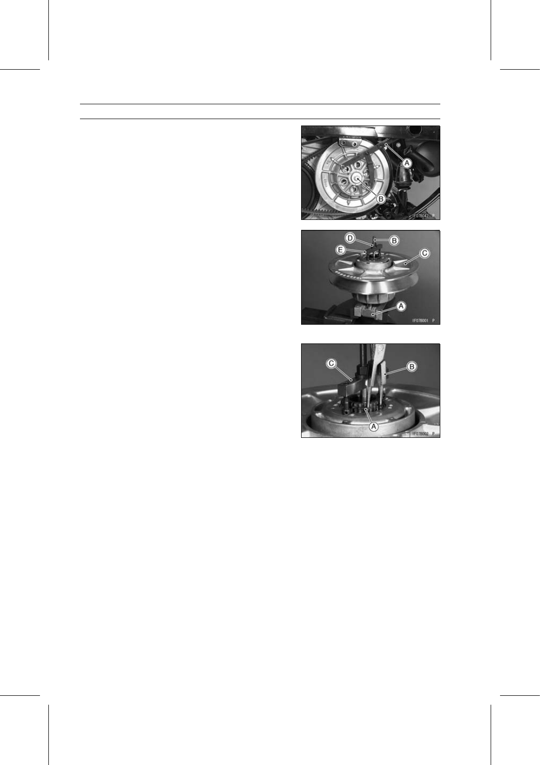
Using a flywheel & pulley holder [A], remove the driven
pulley bolt [B] and stepped collar.

Special Tool - Flywheel & Pulley Holder: 57001-1605

Remove the driven pulley.

Driven Pulley Disassembly

Hold the drive & driven pulley holder [A] in a vise.

Special Tool - Drive & Driven Pulley Holder: 57001-1412

Screw the guide bar [B] of the driven pulley holder into the
holder.

Special Tool - Driven Pulley Holder: 57001-1465

Put the driven pulley [C] on the guide bar.

Tighten the nut [D], and compress the spring with the
spring holder [E] of the driven pulley holder.

Special Tool - Driven Pulley Holder: 57001-1465

Remove the circlip [A] with circlip pliers [B].

Special Tool - Outside Circlip Pliers: 57001-144

Remove the nut and spring holder [C].

CONVERTER SYSTEM 6-25

Driven Pulley

Remove:

Circlip [A]
Washer [B]
Ramp [C]
Spring [D]
Movable Sheave [E]
Spacer [F]
Fixed Sheave with Shaft [G]

Remove:

Wear Shoe Mounting Screws [A]
Wear Shoes [B]

Driven Pulley Inspection

If the sheave surfaces [A] appear damaged, replace the
sheaves.

Replace any sheave which has uneven wear on the belt
contacting surface.

Straight Edge [B]

If the guide bushings [A] are damaged or worn, replace
the movable sheave.

Sheave Bushing Inside Diameter

Standard:

39.655

∼ 39.965 mm (1.561 ∼ 1.573 in.)

Service Limit: 40 mm (1.57 in.)

6-26 CONVERTER SYSTEM

Driven Pulley

If the splines [A] of the fixed sheave and ramp are dam-
aged or worn, replace them.

If the spring is damaged, replace the spring.

Spring Free Length [A]

Standard:

137.5 mm (5.41 in.)

If the tabs on the spring are misaligned or the spring coils
are distorted, replace the spring.

One side end [B] of the spring must be maintained to ±10°
from other side end.

Converter Driven Pulley Shoe Inspection

Refer to the Converter Driven Pulley Shoe Inspection in
the Periodic Maintenance chapter.

CONVERTER SYSTEM 6-27

Driven Pulley

Driven Pulley Assembly

Install the wear shoes [A] on the movable sheave [B] as
shown in the figure.

The wear shoe shall be installed so that the mark [C] on
the shoe faces outward.

Apply a non-permanent locking agent to the wear shoe
mounting screws.

Tighten:

Torque - Wear Shoe Mounting Screws: 1.1 N·m (0.11 kgf·m,

10 in·lb)

Hold the fixed sheave with the drive & driven pulley holder
and driven pulley holder in a vise.

Special Tools - Drive & Driven Pulley Holder: 57001-1412

Driven Pulley Holder: 57001-1465

Install the spacer(s) [A] on the fixed sheave [B].

Install:

Movable Sheave [A]
Spring [B]

Insert the spring end into the hole [C] on the movable
sheave.

Install the ramp [A] on the fixed sheave shaft.

Insert the spring end [B] into the hole “1” on the ramp.

Put the washer [C] and circlip [D] on the ramp.

The washer shall be installed so that the recess of it faces
outward.

Install the spring holder [A].

Align the flat portions [B] of spline of the fixed sheave and
ramp, and push down the ramp halfway by tightening the
flange nut [C].

Hold the movable sheave [D] by turning it counterclock-
wise 120º and tighten the flange nut until the bottom of
ramp hits the movable sheave.

Install the washer and new circlip.

Special Tool - Outside Circlip Pliers: 57001-144

Release the movable sheave slowly until it stops naturally.


Content   ..  41  42  43  44   ..