Kawasaki Diesel MULE 4010 TRANS 4x4 (KAF950G9). Manual - part 34
 

  Index      Engines     Kawasaki Diesel MULE 4010 TRANS 4x4 (KAF950G9) - service manual


Search            


Content   ..  32  33  34  35   ..


Kawasaki Diesel MULE 4010 TRANS 4x4 (KAF950G9). Manual - part 34


5-12 ENGINE TOP END

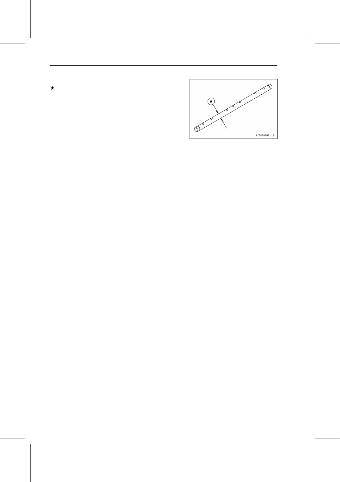
Rocker Shaft and Rocker Arm

Measure the diameter [A] of the rocker shaft.
If the shaft has worn past the service limit, replace the
rocker shaft.

Rocker Shaft Diameter

Standard:

9.97

∼ 9.99 mm (0.3925 ∼ 0.3933 in.)

Service Limit:

9.957 mm (0.3920 in.)

ENGINE TOP END 5-13

Valve Lifters

Valve Lifter Removal

Remove:

Cylinder Head (see Cylinder Head Removal)
Valve Lifters [A]

Mark and record the valve lifter locations so that they can
be installed in their original positions.

Valve Lifter Installation

Apply engine oil and install the valve lifters (original posi-
tions).

Valve Lifter Inspection

Measure the outside diameter of the valve lifters [A].
If the valve lifter has worn past the service limit, replace
the lifter.

Valve Lifter Outside Diameter

Standard:

17.98 mm (0.7079 in.)

Service Limit:

17.91 mm (0.7051 in.)

5-14 ENGINE TOP END

Valves

Valve Clearance Inspection

Refer to the Valve Clearance Inspection in the Periodic
Maintenance chapter.

Valve Clearance Adjustment

Refer to the Valve Clearance Adjustment in the Periodic
Maintenance chapter.

Valve Removal

Remove:

Cylinder Head (see Cylinder Head Removal)
Valve Stem Cap

Mark and record the valve stem cap locations so they can
be installed in their original positions.

Using the valve spring compressor [A] remove the split
keepers.

Special Tool - Valve Spring Compressor: 57001-1433

Remove:

Retainer [A]
Valve Spring [B]

Remove:

Valve [A]
Spring Seat [B]
Oil Seal [C]

Valve Installation

Replace the oil seal [A] with a new one.

Apply engine oil to the new oil seal.

Apply a thin coat of molybdenum disulfide grease to the
valve stem before valve installation.

Install:

Oil Seal
Valve [B]
Spring Seat [C]
Valve Spring [D]
Retainer [E]
Split Keepers [F]

ENGINE TOP END 5-15

Valves

Valve Guide Removal

Remove:

Valve (see Valve Removal)
Spring Seat
Oil Seal

Hammer lightly on the valve guide arbor [A] to remove the
guide from the top of the head.

Special Tool - Valve Guide Arbor, 5.5: 57001-1021

Valve Guide Installation

Apply engine oil to the valve guide outer surface before
installation.

Press the valve guide [A] in from the top of the head us-
ing the valve guide driver [B] until the driver bottoms on
cylinder head.

Special Tool - Valve Guide Driver: 57001-1432

Valve Seat Inspection

Remove the valve (see Valve Removal).

Coat the valve seat with machinist’s dye.

Push the valve into the guide.

Rotate the valve against the seat with a lapping tool.

Pull the valve out, and check the seating pattern on the
valve head. It must be the correct width [A] and even all
the way around.

NOTE

The valve stem and guide must be in good condition, or
this check will not be valid.

If the valve seating pattern is not correct, repair the seat.

Measure the outside diameter [B] of the seating pattern
on the valve seat.
If the outside diameter of the valve seating pattern is too
large or too small, repair the seat.

Valve Seating Surface [C]

Too Wide [G]

Valve [D]

Too Narrow [H]

Valve Seat [E]

Uneven [I]

Good [F]

Valve Seating Surface Width

Standard:

0.8

∼ 1.2 mm (0.0315 ∼ 0.0472 in.)

Valve Seating Surface Outside Diameter

Inlet:

28 mm (1.1024 in.)

Exhaust:

24.5 mm (0.9646 in.)


Content   ..  32  33  34  35   ..