Kawasaki Diesel MULE 4010 TRANS 4x4 (KAF950G9). Manual - part 35
 

  Index      Engines     Kawasaki Diesel MULE 4010 TRANS 4x4 (KAF950G9) - service manual


Search            


Content   ..  33  34  35  36   ..


Kawasaki Diesel MULE 4010 TRANS 4x4 (KAF950G9). Manual - part 35


5-16 ENGINE TOP END

Valves

Valve Seat Repair

Follow the manufacturer’s instructions for use of valve
seat cutters.

Special Tools - Valve Seat Cutter Holder, 5.5: 57001-1125

Valve Seat Cutter Holder Bar: 57001-1128

[For Inlet Valve Seat]

Valve Seat Cutter, 45° - 27.5: 57001-1114
Valve Seat Cutter, 60° - 30: 57001-1123

[For Exhaust Valve Seat]

Valve Seat Cutter, 32° - 28: 57001-1119
Valve Seat Cutter, 30° - 30: 57001-1120

If the manufacturer’s instructions are not available, use
the following procedure.

Seat Cutter Operation Care
1. This valve seat cutter is developed to grind the valve for

repair. Therefore the cutter must not be used for other
purposes than seat repair.

2. Do not drop or shock the valve seat cutter, or the dia-

mond particles may fall off.

3. Do not fail to apply engine oil to the valve seat cutter

before grinding the seat surface. Also wash off ground
particles sticking to the cutter with washing oil.

NOTE

Do not use a wire brush to remove the metal particles
from the cutter. It will take off the diamond particles.

4. Setting the valve seat cutter holder in position, operate

the cutter in one hand. Do not apply too much force to
the diamond portion.

NOTE

Prior to grinding, apply engine oil to the cutter and dur-
ing the operation, wash off any ground particles sticking
to the cutter with washing oil.

5. After use, wash it with washing oil and apply thin layer

of engine oil before storing.

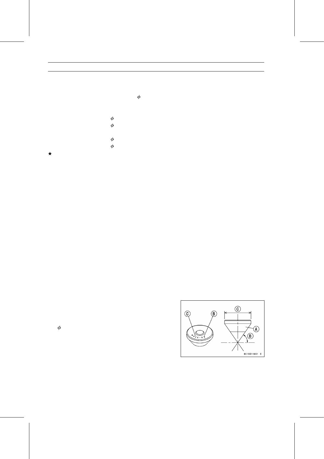
Marks Stamped on the Cutter

The marks stamped on the back of the cutter [A] represent

the following.
60° ........................... Cutter angle [B]
37.5

....................... Outer diameter of cutter [C]

ENGINE TOP END 5-17

Valves

Operating Procedures

Clean the seat area carefully.

Coat the seat with machinist’s dye.

Fit a 45° cutter into the holder and slide it into the valve
guide.

Press down lightly on the handle and turn it right or left.
Grind the seating surface only until it is smooth.

NOTICE

Do not grind the seat too much. Overgrinding will
reduce valve clearance by sinking the valve into the
head. If the valve sinks too far into the head, it will
be impossible to adjust the clearance, and the cylin-
der head must be replaced.

Measure the outside diameter of the seating surface with
a vernier caliper.
If the outside diameter of the seating surface is too small,
repeat the 45° grind until the diameter is within the spec-
ified range.

Widened Width [A] of engagement by machining with
45° cutter
Ground Volume [B] by 32° cutter
32° [C]
Correct Width [D]
Ground Volume [E] by 60° cutter
60° [F]

Measure the outside diameter of the seating surface with
a vernier caliper.
If the outside diameter of the seating surface is too small,
repeat the 45° grind [A] until the diameter is within the
specified range.

Original Seating Surface [B]

NOTE

Remove all pittings of flaws from 45° ground surface.

After grinding with 45° cutter, apply thin coat of machin-
ist’s dye to seating surface. This makes seating surface
distinct and 32° and 60° grinding operation easier.

When the valve guide is replaced, be sure to grind with
45° cutter for centering and good contact.

5-18 ENGINE TOP END

Valves

If the outside diameter [A] of the seating surface is too
large, make the 32° grind described below.
If the outside diameter of the seating surface is within the
specified range, measure the seat width as described be-
low.

Grind the seat at a 32° angle [B] until the seat outside
diameter is within the specified range.

To make the 32° grind, fit a 32° cutter into the holder, and
slide it into the valve guide.

Turn the holder one turn at a time while pressing down
very lightly. Check the seat after each turn.

NOTICE

The 32° cutter removes material very quickly.
Check the seat outside diameter frequently to pre-
vent overgrinding.

After making the 32° grind, return to the seat outside di-
ameter measurement step above.

To measure the seat width, use a vernier caliper to mea-
sure the width of the 45° angle portion of the seat at sev-
eral places around the seat.
If the seat width is too narrow, repeat the 45° grind until
the seat is slightly too wide, and then return to the seat
outside diameter measurement step above.

If the seat width is too wide, make the 60° [A] grind de-
scribed below.
If the seat width is within the specified range, lap the valve
to the seat as described below.

Grind the seat at a 60° angle until the seat width is within
the specified range.

To make the 60° grind, fit 60° cutter into the holder, and
slide it into the valve guide.

Turn the holder, while pressing down lightly.

After making the 60° grind, return to the seat width mea-
surement step above.

Correct Width [B]

ENGINE TOP END 5-19

Valves

Lap the valve to the seat, once the seat width and outside
diameter are within the ranges specified above.

Put a little coarse grinding compound on the face of the
valve in a number of places around the valve head.

Spin the valve against the seat until the grinding com-
pound produces a smooth, matched surface on both the
seat and the valve.

Repeat the process with a fine grinding compound.

Lapper [A]
Valve Seat [B]
Valve [C]

The seating area should be marked about in the middle
of the valve face.
If the seat area is not in the right place on the valve, check
to be sure the valve is the correct part. If it is, it may have
been refaced too much; replace it.

Be sure to remove all grinding compound before assem-
bly.

When the engine is assembled, be sure to adjust the valve
clearance (see Valve Clearance Inspection in the Periodic
Maintenance chapter).


Content   ..  33  34  35  36   ..