Kawasaki Diesel MULE 4010 TRANS 4x4 (KAF950G9). Manual - part 33
 

  Index      Engines     Kawasaki Diesel MULE 4010 TRANS 4x4 (KAF950G9) - service manual


Search            


Content   ..  31  32  33  34   ..


Kawasaki Diesel MULE 4010 TRANS 4x4 (KAF950G9). Manual - part 33


5-8 ENGINE TOP END

Cylinder Head

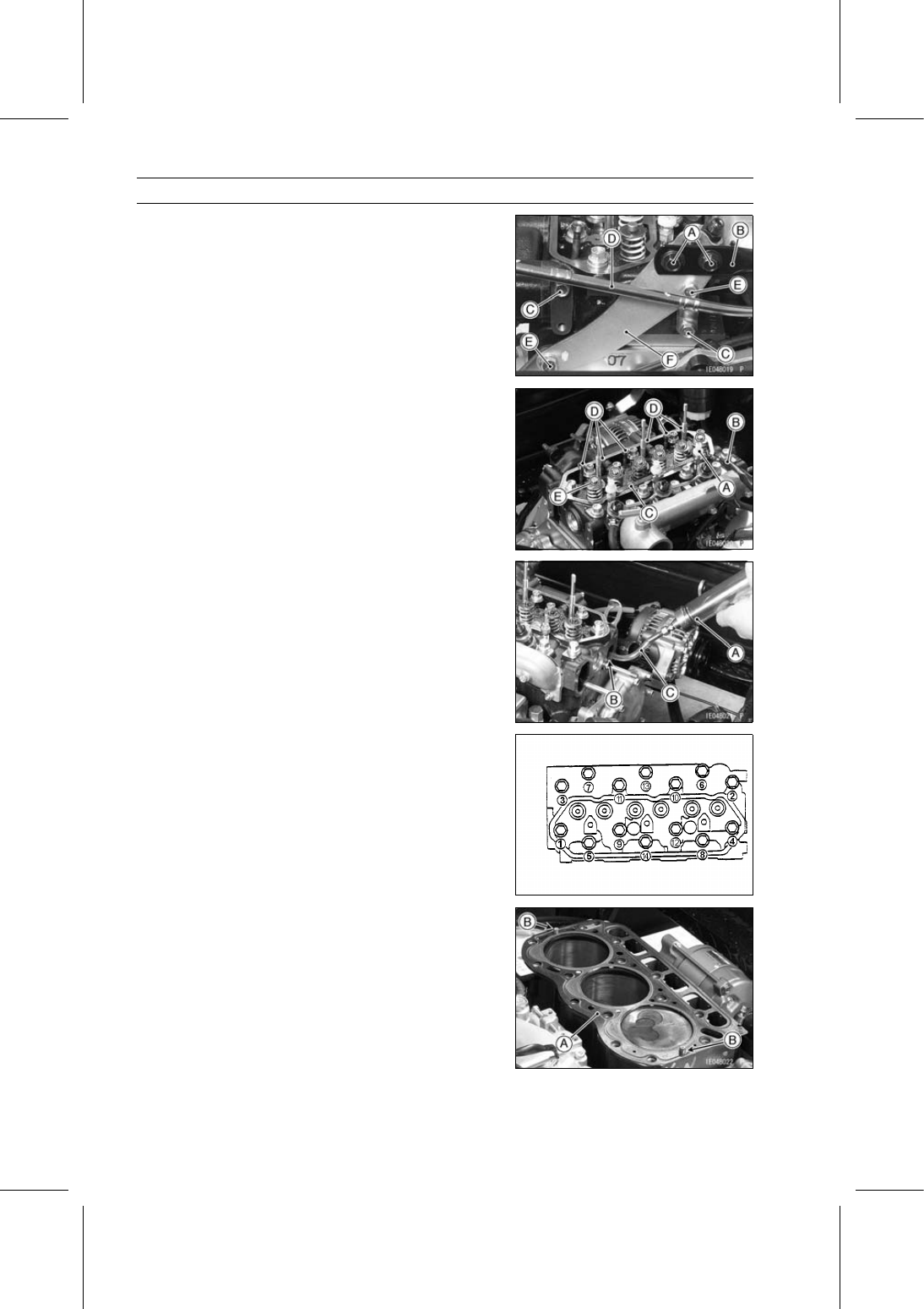
Remove:

Bolts [A] and Nuts
Engine Mount Stay [B]
Bolts [C]
Oil Level Gauge Pipe [D]
Bolts [E]
Plate [F]

Remove:

Glow Plug Caps [A]
Glow Plug Lead [B]
Glow Plug Connecting Plate [C]
Rocker Arm Push Rods [D]
Valve Stem Caps [E]

Mark the push rods so that they may be installed in their
original positions.

Remove the coolant from the cylinder head, using a
syringe [A] or some other suitable device, through the
coolant inlet opening [B].

Insert the gauge tube [C] 10

∼ 11 cm (3.9 ∼ 4.3 in.) from

the opening.

Pull the handle slowly to pump out the coolant until the
coolant no longer comes out.

Remove the cylinder head bolts following loosening se-
quence [1

∼ 14].

Remove:

Cylinder Head
Cylinder Head Gasket

Cylinder Head Installation

Clean the mating surface of the cylinder head and the
cylinder.

Replace the cylinder head gasket [A] with a new one.

Install the dowel pins [B].

ENGINE TOP END 5-9

Cylinder Head

Apply engine oil to the cylinder head bolts.

Tighten the cylinder head bolts in the order shown.

Torque - Cylinder Head Bolts: 34 N·m (3.5 kgf·m, 25 ft·lb)

Apply engine oil and install the rocker arm push rods [A]
(in original locations if reused).

Face the recessed end [B] upward.

Install:

Valve Stem Caps
Rocker Arm Components (see Rocker Arm Components
Installation)

Inspect the valve clearance (see Valve Clearance Inspec-
tion in the Periodic Maintenance chapter).

Install the removed parts (see appropriate chapters).

Cylinder Head Warp

Clean the cylinder head.

Lay a straightedge [A] across the lower surface, inlet and
exhaust manifold mounting surface of the head at several
different points, and measure warp by inserting a thick-
ness gauge [B] between the straightedge and the head.
If warp exceeds the service limit, repair the mating sur-
face. Replace the cylinder head if the mating surface is
badly damaged.

Cylinder Head Warp

Service Limit:

0.1 mm (0.004 in.)

5-10 ENGINE TOP END

Rocker Shaft and Rocker Arm

Rocker Arm Components Removal

Remove:

Fan Belt Cover (see Cooling Fan Belt Inspection in the
Periodic Maintenance chapter)
Breather Hose [A]
Cylinder Head Cover Bolts [B] and Washers [C]
Cylinder Head Cover [D]

Turn the crankshaft pulley [A] clockwise so that the timing
mark [B] on the pulley aligns with the reference point [C]
on the timing cover.

Check that the rocker arms at #1 cylinder are free.
If not, turn the pulley one more turn to free the rocker
arms.

Remove:

Rocker Arm Components Mounting Nuts [A] and Wash-
ers [B]
Rocker Arm Components [C]

Rocker Arm Components Installation

Install the rocker arm components.

Torque - Rocker Arm Components Mounting Nuts: 20 N·m

(2.0 kgf·m, 15 ft·lb)

Inspect the valve clearance (see Valve Clearance Inspec-
tion in the Periodic Maintenance chapter).

Tighten:

Torque - Cylinder Head Cover Nuts: 5.4 N·m (0.55 kgf·m, 48

in·lb)

Install the breather hose [A].

Twist the breather hose so that the white marks [B] face
upward and the center part is higher than both ends.

ENGINE TOP END 5-11

Rocker Shaft and Rocker Arm

Rocker Arm Components Disassembly

Remove:

Rocker Arm Components (see Rocker Arm Components
Removal)
Circlips [A]

Special Tool - Outside Circlip Pliers [B]: 57001-144

Remove:

Rocker Arms [A]
Rocker Arm Supports [B]
Washers [C]
Springs [D]
Set Bolt [E]
Rocker Shaft [F]

Rocker Arm Components Assembly

Apply engine oil to the all components.

Small grooves next to oil holes [A] in the rocker shaft [B]
must face down.

Install the center rocker arm support [C] as shown in the
figure, and tighten the set bolt.

Left Lower Oil Hole [D]

Install:

Rocker Arms [A]
Springs [B]
Rocker Arm Supports [C]
Washers [D]
New Circlips [E]

Special Tool - Outside Circlip Pliers: 57001-144

Rocker Arm/Shaft Wear

Measure the inside diameter [A] of the rocker arm.
If the bearing has worn past the service limit, replace the
rocker arm.

Rocker Arm Inside Diameter

Standard:

10.00

∼ 10.02 mm (0.3937 ∼ 0.3945 in.)

Service Limit:

10.03 mm (0.3949 in.)


Content   ..  31  32  33  34   ..