Kawasaki Diesel MULE 4010 TRANS 4x4 (KAF950G9). Manual - part 30
 

  Index      Engines     Kawasaki Diesel MULE 4010 TRANS 4x4 (KAF950G9) - service manual


Search            


Content   ..  28  29  30  31   ..


Kawasaki Diesel MULE 4010 TRANS 4x4 (KAF950G9). Manual - part 30


4-12 COOLING SYSTEM

Radiator and Radiator Fan

Radiator Inspection

Check the radiator core.
If there are obstructions to air flow, remove them.
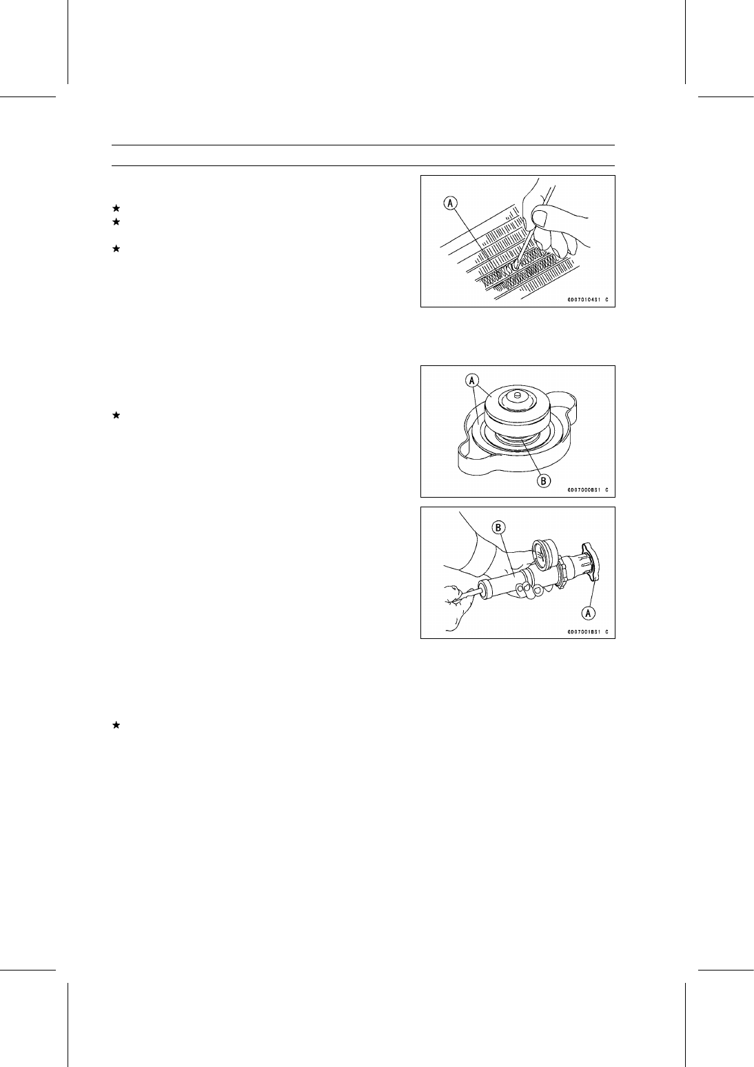
If the corrugated fins [A] are deformed, carefully
straighten them.
If the air passages of the radiator core are blocked more
than 20% by unremovable obstructions or irreparable de-
formed fins, replace the radiator.

Radiator Cleaning

Refer to the Radiator Cleaning in the Periodic Mainte-
nance chapter.

Radiator Cap Inspection

Check the condition of the radiator cap valve seals [A] and
valve spring [B].
If any one of them shows visible damage, replace the cap
with a new one.

Install the cap [A] on a cooling system pressure tester [B].

NOTE

Wet the cap sealing surfaces with water or coolant to
prevent pressure leakage.

Watching the pressure gauge, slowly pump the pressure
tester to build up the pressure. The gauge pointer must
remain within the relief pressure range in the table below
at least 6 seconds. Continue to pump the tester until the
relief valve opens, indicated by the gauge pointer flicking
downward. The relief valve must open within the specified
range.

Radiator Cap Relief Pressure

Standard:

93

∼ 123 kPa (0.95 ∼ 1.25 kgf/cm², 13

∼ 18 psi)

If the cap cannot hold the specified pressure, or if it holds
too much pressure, replace the cap.

COOLING SYSTEM 4-13

Thermostat

Thermostat Removal

Tilt up the cargo bed.

Drain the coolant (see Coolant Change in the Periodic
Maintenance chapter).

Remove:

Coolant Temperature Switch Lead Connector [A]
Thermostat Housing Cap Bolts [B]
Thermostat Housing Cap [C]

Remove:

Locating Screw [A]
Thermostat [B]

Thermostat Installation

Replace the thermostat housing gasket with a new one.

Install the locating screw.

Tighten:

Torque - Thermostat Housing Cap Bolts: 7.8 N·m (0.80

kgf·m, 69 in·lb)

Adjust the coolant (see Coolant Change in the Periodic
Maintenance chapter).

Thermostat Inspection

Remove the thermostat, and inspect the thermostat valve
[A] at room temperature.
If the valve is open, replace the thermostat with a new
one.

To check valve opening temperature, suspend the ther-
mostat [A] in a container of water and raise the tempera-
ture of the water.

The thermostat must be completely submerged and must
not touch the container sides or bottom. Suspend an ac-
curate thermometer [B] in the water. It must not touch the
container, either.
If the measurement is out of the specified range, replace
the thermostat with a new one.

Thermostat Valve Opening Temperature

Standard:

81

∼ 84°C (178 ∼ 183°F)

Thermostat Valve Full Opening Temperature

Standard:

95°C (203°F)

4-14 COOLING SYSTEM

Hoses and Pipes

Hose and Pipe Installation

Install the hoses and pipes being careful to follow bend-
ing direction or diameter. Avoid sharp bending, kinking,
flattening, or twisting.

Install the clamps [A] as near as possible to the hose end
to clear the raised rib or the fitting. This will prevent the
hoses from working loose.

The clamp screws should be positioned correctly to pre-
vent the clamps from contacting anything.

Install the water pipes [A].

Tighten:

Torque - Water Pipe Mounting Bolts [B]: 8.8 N·m (0.90

kgf·m, 78 in·lb)

Hose Inspection

Refer to the Radiator Hose and Connection Inspection in
the Periodic Maintenance chapter.

COOLING SYSTEM 4-15

Radiator Fan Switch, Coolant Temperature Switch

Radiator Fan Switch Removal

NOTICE

The fan switch or the coolant temperature switch
should never be allowed to fall on a hard surface.
Such a shock to their parts can damage them.

Drain the coolant (see Coolant Change in the Periodic
Maintenance chapter).

Remove the front cover (see Front Cover Removal in the
Frame chapter).

Turn over the rubber cover [A].

Remove:

Radiator Fan Switch Lead Connectors [B]
Radiator Fan Switch [C]

Coolant Temperature Switch Removal

Tilt up the cargo bed.

Remove:

Coolant Temperature Switch Lead Connector [A]
Coolant Temperature Switch [B]

Radiator Fan Switch, Coolant Temperature Switch

Installation

Apply grease to the O-ring on the fan switch.

Apply a non-permanent locking agent to the threads of
the coolant temperature switch.

Tighten the fan switch and coolant temperature switch.

Torque - Radiator Fan Switch: 25 N·m (2.5 kgf·m, 18 ft·lb)

Coolant Temperature Switch: 27 N·m (2.8 kgf·m,

20 ft·lb)

Radiator Fan Switch Inspection

Refer to the Radiator Fan Switch Inspection in the Elec-
trical System chapter.

Coolant Temperature Switch Inspection

Refer to the Coolant Temperature Switch Inspection in the
Electrical System chapter.


Content   ..  28  29  30  31   ..