Kawasaki Diesel MULE 4010 TRANS 4x4 (KAF950G9). Manual - part 28
 

  Index      Engines     Kawasaki Diesel MULE 4010 TRANS 4x4 (KAF950G9) - service manual


Search            


Content   ..  26  27  28  29   ..


Kawasaki Diesel MULE 4010 TRANS 4x4 (KAF950G9). Manual - part 28


4-4 COOLING SYSTEM

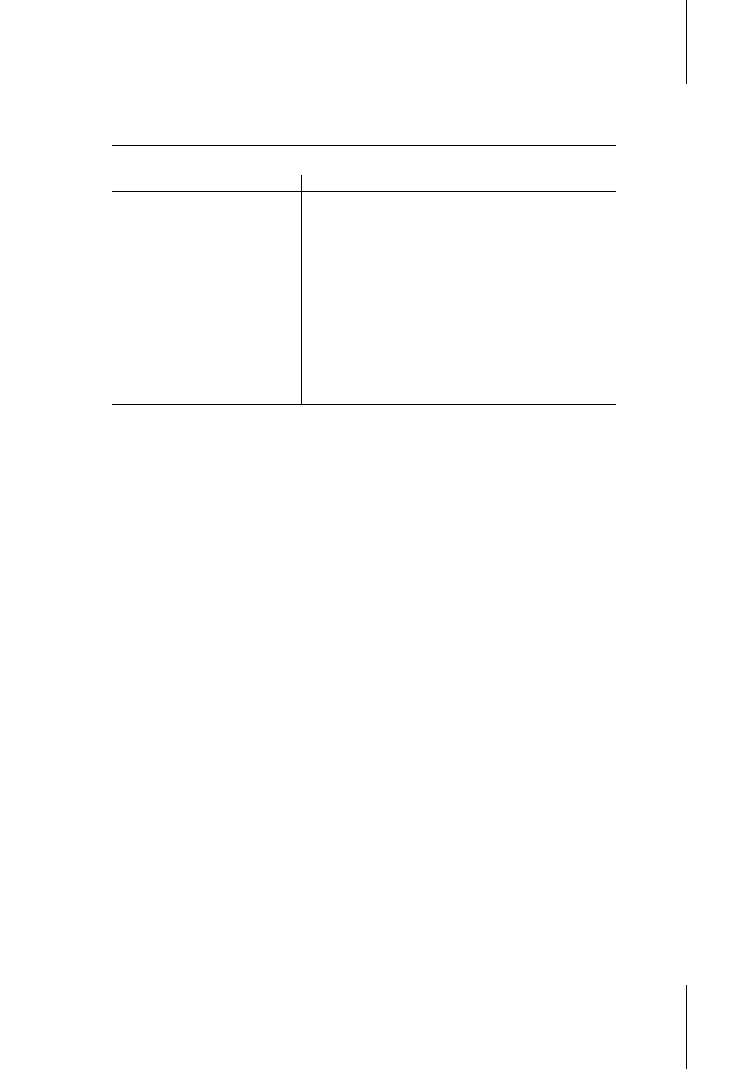
Specifications

Item

Standard

Coolant

Type (Recommended)

Permanent type of antifreeze (soft water and ethylene glycol
plus corrosion and rust inhibitor chemicals for aluminum
engines and radiators)

Color

Green

Mixed Ratio

Soft water 50%, coolant 50%

Freezing Point

–35°C (–31°F)

Total Amount

4.4 L (4.7 US qt)

Radiator Cap

Relief Pressure

93

∼ 123 kPa (0.95 ∼ 1.25 kgf/cm², 13 ∼ 18 psi)

Thermostat

Valve Opening Temperature

81

∼ 84°C (178 ∼ 183°F)

Valve Full Opening Temperature

95°C (203°F)

COOLING SYSTEM 4-5

Flow Chart

This engine has a pressurized, forced circulation cooling system.
The water pump circulates coolant through the cylinder block, cylinder head and radiator. The ther-

mostat maintains optimum engine temperature.

The thermostat is equipped with a by-pass valve which permits coolant to re-circulate through the

cylinder block and cylinder head.

As the engine warms, the by-pass valve closes as the thermostat opens, permitting complete cir-

culation through the radiator.

Always maintain a 50% solution of phosphate free antifreeze at all times for adequate heat dissipa-

tion, lubrication and protection from freezing.

1. Water Pump
2. Thermostat
3. Air Bleed Bolt
4. Reserve Tank
5. Radiator
6. Radiator Cap
7. Drain Bolts
8. Front

4-6 COOLING SYSTEM

Coolant

Coolant Level Inspection

NOTE

Check the level when the engine is cold (room of ambi-
ent temperature).

NOTICE

Do not check the level through the coolant filler by
removing the radiator cap. If the cap is removed,
the coolant will flow out from the reserve tank.

Tilt up the front cargo hood.

Check the coolant level in the reserve tank [A] with the
vehicle parked on a level surface.
If the coolant level is lower than the L (Low) level line [C],
remove the reserve tank cap [B], then add coolant to the
F (Full) level line [D].

NOTICE

For refilling, add the specified mixture of coolant
and soft water.

Adding water alone dilutes the

coolant and degrades its anticorrosion properties.
The diluted coolant can attack the aluminum engine
parts. In an emergency, soft water can be added.
But the diluted coolant must be returned to the cor-
rect mixture ratio within a few days.
If coolant must be added often, or the reserve tank
has run completely dry; there is probably leakage
in the cooling system. Check the system for leaks.

Coolant Draining

Refer to the Coolant Change in the Periodic Maintenance
chapter.

Coolant Filling

Refer to the Coolant Change in the Periodic Maintenance
chapter.

Coolant Reserve Tank Removal

Tilt up the front cargo hood.

Remove:

Quick Rivets [A]
Tapping Screw [B] and Collar
Partition [C]

COOLING SYSTEM 4-7

Coolant

Remove the coolant reserve tank mounting bolts [A].

Remove the cap and poor the coolant into a container.

Remove:

Reserve Tank Overflow Hose [B]
Radiator Overflow Hose [C]
Coolant Reserve Tank

Coolant Reserve Tank Installation

Installation is the reverse of removal, note the following.

Insert the projection [A] of the coolant reserve tank into
the grommet [B] on the font cargo compartment.

Run the hoses according to the Cable, Wire, and Hose
Routing section in the Appendix chapter.

Fill the coolant reserve tank with coolant (see Coolant
Change in the Periodic Maintenance chapter).


Content   ..  26  27  28  29   ..