Kawasaki Diesel MULE 4010 TRANS 4x4 (KAF950G9). Manual - part 27
 

  Index      Engines     Kawasaki Diesel MULE 4010 TRANS 4x4 (KAF950G9) - service manual


Search            


Content   ..  25  26  27  28   ..


Kawasaki Diesel MULE 4010 TRANS 4x4 (KAF950G9). Manual - part 27


3-38 FUEL SYSTEM

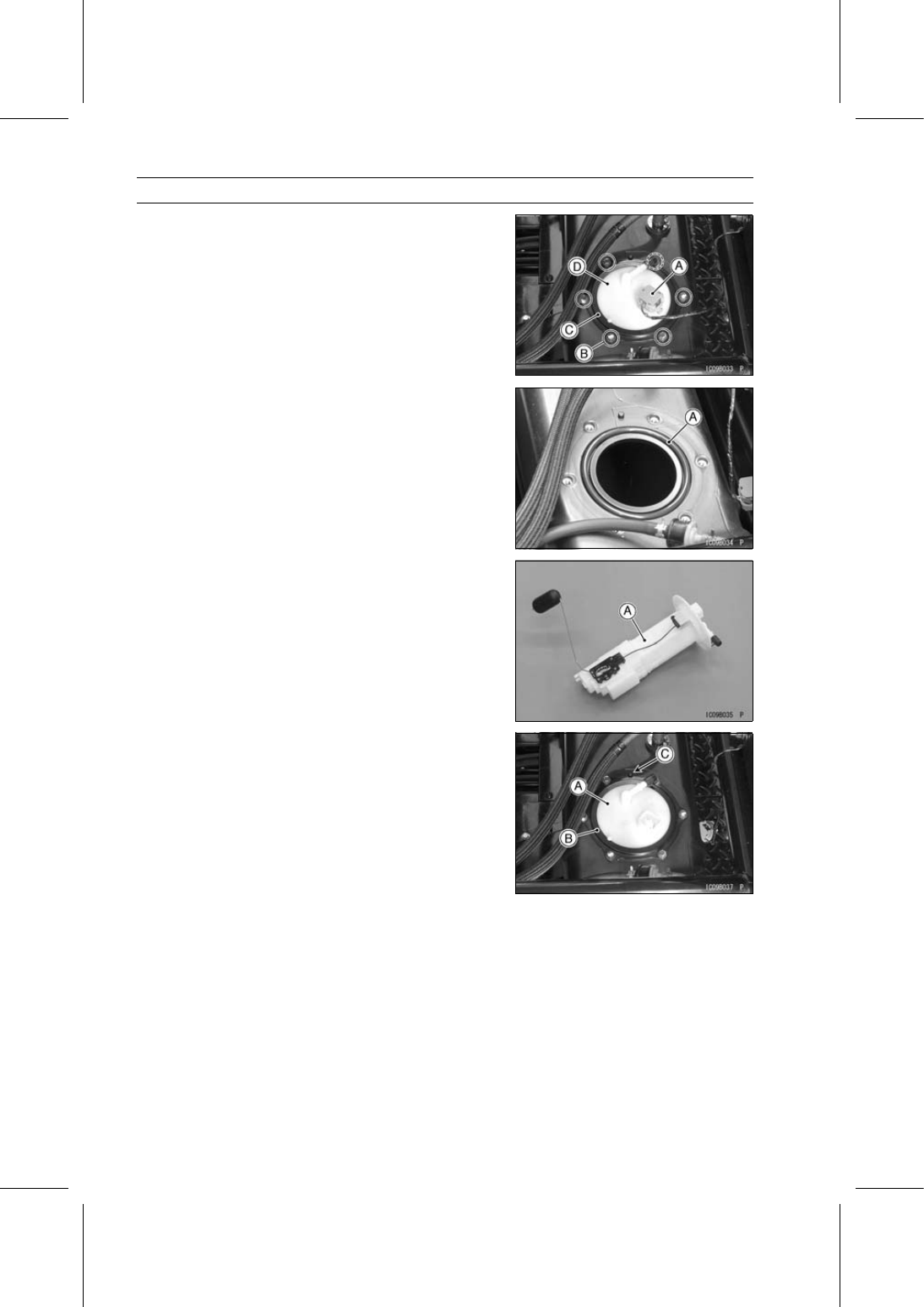
Fuel Tank

Remove:

Fuel Level Gauge Lead Connector [A]
Fuel Level Gauge Mounting Bolts [B]
Plate [C]
Fuel Level Gauge [D]

Discard the O-ring [A].

Fuel Level Gauge Installation (KAF950GD)

Remove dirt or dust from the fuel level gauge [A] by lightly
applying compressed air.

Replace the O-ring with a new one and install it in the
groove on the fuel tank.

Install the fuel level gauge [A] and plate [B], so that the
projections [C] fit into the recesses.

Tighten:

Torque - Fuel Level Gauge Mounting Bolts: 4.0 N·m (0.41

kgf·m, 35 in·lb)

COOLING SYSTEM 4-1

4

Cooling System

Table of Contents

Exploded View........................................................................................................................

4-2

Specifications .........................................................................................................................

4-4

Flow Chart ..............................................................................................................................

4-5

Coolant ...................................................................................................................................

4-6

Coolant Level Inspection...................................................................................................

4-6

Coolant Draining ...............................................................................................................

4-6

Coolant Filling ...................................................................................................................

4-6

Coolant Reserve Tank Removal .......................................................................................

4-6

Coolant Reserve Tank Installation ....................................................................................

4-7

Water Pump............................................................................................................................

4-8

Water Pump Removal.......................................................................................................

4-8

Water Pump Installation....................................................................................................

4-8

Water Pump Inspection.....................................................................................................

4-9

Radiator and Radiator Fan .....................................................................................................

4-10

Radiator Removal .............................................................................................................

4-10

Radiator Installation ..........................................................................................................

4-11

Radiator Fan Removal ......................................................................................................

4-11

Radiator Fan Installation ...................................................................................................

4-11

Radiator Inspection ...........................................................................................................

4-12

Radiator Cleaning .............................................................................................................

4-12

Radiator Cap Inspection ...................................................................................................

4-12

Thermostat .............................................................................................................................

4-13

Thermostat Removal.........................................................................................................

4-13

Thermostat Installation......................................................................................................

4-13

Thermostat Inspection .....................................................................................................

4-13

Hoses and Pipes ....................................................................................................................

4-14

Hose and Pipe Installation ................................................................................................

4-14

Hose Inspection ................................................................................................................

4-14

Radiator Fan Switch, Coolant Temperature Switch ................................................................

4-15

Radiator Fan Switch Removal ..........................................................................................

4-15

Coolant Temperature Switch Removal..............................................................................

4-15

Radiator Fan Switch, Coolant Temperature Switch Installation ........................................

4-15

Radiator Fan Switch Inspection ........................................................................................

4-15

Coolant Temperature Switch Inspection ...........................................................................

4-15

4-2 COOLING SYSTEM

Exploded View

COOLING SYSTEM 4-3

Exploded View

Torque

No.

Fastener

N·m

kgf·m

ft·lb

Remarks

1 Coolant Drain Plug

25

2.5

18

L

2 Coolant Inlet Bolts

7.8

0.80

69 in·lb

3 Coolant Reserve Tank Bolt

4.4

0.45

39 in·lb

4 Coolant Temperature Switch

27

2.8

20

L

5 Fan Mounting Bolts

8.8

0.90

78 in·lb

6 Radiator Fan Mounting Bolts

6.0

0.61

53 in·lb

7 Radiator Fan Switch

23

2.3

17

8 Radiator Fan Switch

25

2.5

18

9 Radiator Mounting Bolts

8.8

0.90

78 in·lb

10 Radiator Screen Mounting Bolts

8.8

0.90

78 in·lb

11 Shroud Mounting Bolts

6.0

0.61

53 in·lb

12 Thermostat Housing Cap Bolts

7.8

0.80

69 in·lb

13 Water Pipe Mounting Bolts

8.8

0.90

78 in·lb

14 Water Pump Mounting Bolts and Nuts

20

2.0

15

15. Blue Marks: Install the hoses so that their marks face upwards.
16. KAF950G9, GA/HA

G: Apply grease.

L: Apply a non-permanent locking agent.

R: Replacement Parts


Content   ..  25  26  27  28   ..