Kawasaki Diesel MULE 4010 TRANS 4x4 (KAF950G9). Manual - part 21
 

  Index      Engines     Kawasaki Diesel MULE 4010 TRANS 4x4 (KAF950G9) - service manual


Search            


Content   ..  19  20  21  22   ..


Kawasaki Diesel MULE 4010 TRANS 4x4 (KAF950G9). Manual - part 21


3-14 FUEL SYSTEM

Fuel Injection Nozzle

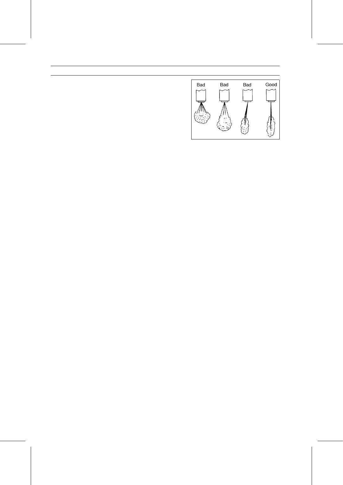
Ensure that the fuel spray forms a cone shape while the
“buzzing” is occurring, and that the center of the cone is
aligned with the center line of the nozzle.

Ensure that the nozzle does not drip.

FUEL SYSTEM 3-15

Fuel Injection Pump

Idle Speed Inspection

Refer to the Idle Speed Inspection in the Periodic Main-
tenance chapter.

Idle Speed Adjustment

Refer to the Idle Speed Adjustment in the Periodic Main-
tenance chapter.

Maximum Engine Speed Inspection

Check the full throttle pedal position (see Full Throttle
Pedal Position Adjustment).

Set the parking brake.

Be sure the transmission is in neutral.

Start the engine and warm it up thoroughly.

Tilt up the cargo bed.

Check the maximum engine speed with a suitable
tachometer.

Maximum Engine Speed (No Load)

Standard: 3 800

∼ 3 900 r/min (rpm)

If the maximum engine speed is not in the specified range,
adjust it.

Maximum Engine Speed Adjustment

Set the parking brake.

Be sure the transmission is in neutral.

Tilt up the cargo bed.

Remove the fuel injection pump cover (see Full Throttle
Pedal Position Adjustment).

Cut and remove the wire [A] on the maximum speed set
screw [B].

Start the engine and warm it up thoroughly.

Loosen the locknut [C].

Turn the maximum speed set screw until the maximum
engine speed is correct.

Tighten:

Torque - Maximum Speed Set Screw Locknut: 6.9 N·m (0.70

kgf·m, 61 in·lb)

Lock the maximum speed set screw with a wire or paint
on the locknut and pump housing.

Fuel Injection Pipe Removal

WARNING

Fuel is extremely flammable and can be explosive
under certain conditions. Turn the main switch off.
Do not smoke. Make sure the area is well ventilated
and free from any source of flame or sparks; this
includes any appliance with a pilot light.

NOTICE

Take care to prevent any dirt from entering injection
nozzle holes or delivery valve ports when fuel deliv-
ery lines are removed.

3-16 FUEL SYSTEM

Fuel Injection Pump

Cut the bands [A].

Remove:

Air Duct Mounting Screw [B]
Air Duct [C]

Remove the air duct [A].

Remove:

Fuel Injection Pipe Clamp Bolts [A]
Fuel Injection Pipe Clamps [B]

Loosen the fuel injection pipe upper nuts [C].

Remove:

Fuel Injection Pipe No. 3 Lower Nut [A] and Upper Nut
Fuel Injection Pipe No. 1 Lower Nut [B] and Upper Nut
Fuel Injection Pipe No. 2 Lower Nut [C] and Upper Nut

Fuel Injection Pipe Installation

Install the fuel injection pipes using the following steps.

First, install the No. 2 injection pipe [A].

Secondly, install the No. 1 injection pipe.

Finally, install the No. 3 injection pipe.

NOTE

Tighten the upper and lower nuts temporarily and then
tighten them to the specified torque.

Tighten:

Torque - Fuel Injection Pipe Mounting Nuts: 25 N·m (2.5

kgf·m, 18 ft·lb)

Fuel Injection Pipe Clamp Bolts: 7.4 N·m (0.75

kgf·m, 65 in·lb)

FUEL SYSTEM 3-17

Fuel Injection Pump

Fuel Injection Pump Removal

Remove:

Engine (see Engine Removal in the Engine Removal/In-
stallation chapter)
Fuel Injection Pump Drive Gear (see Timing Gear Case
Removal in the Crankshaft/Crankcase chapter)
Fuel Injection Pipes (see Fuel Injection Pipe Removal)
Fuel Return Hose [A]
Fuel Injection Pump Bracket Bolts [B]
Fuel Injection Pump Bracket [C]

Remove:

Fuel Injection Pump Mounting Nuts [A]
Fuel Injection Pump [B]

Fuel Injection Pump Installation

Replace the O-ring [A] with a new one.

Apply grease to the new O-ring.

Install the fuel injection pump temporary.

Align the timing marks [A] on the injection pump and tim-
ing gear case.

Tighten the mounting nuts with fingers.


Content   ..  19  20  21  22   ..