Kawasaki Diesel MULE 4010 TRANS 4x4 (KAF950G9). Manual - part 22
 

  Index      Engines     Kawasaki Diesel MULE 4010 TRANS 4x4 (KAF950G9) - service manual


Search            


Content   ..  20  21  22  23   ..


Kawasaki Diesel MULE 4010 TRANS 4x4 (KAF950G9). Manual - part 22


3-18 FUEL SYSTEM

Fuel Injection Pump

Install:

Fuel Injection Pump Drive Gear, Timing Gear Case
Cover and Crankshaft Pulley (see Timing Gear Case
Installation in the Crankshaft/Crankcase chapter)

Adjust the fuel injection pump timing (see Fuel Injection
Pump Timing Inspection).

Tighten:

Torque - Fuel Injection Pipe Mounting Nuts: 25 N·m (2.5

kgf·m, 18 ft·lb)

Fuel Injection Pipe Clamp Bolts: 7.4 N·m (0.75

kgf·m, 65 in·lb)

Adjust:

Maximum Engine Speed (New Injection Pump) (see
Maximum Engine Speed Adjustment)
Idle Speed (see Idle Speed Adjustment in the Periodic
Maintenance chapter)

Fuel Injection Pump Timing Inspection

Remove:

Fan Belt Cover (see Cooling Fan Belt Inspection in the
Periodic Maintenance chapter)
Fuel Injection Pipes (see Fuel Injection Pipe Removal)
Cylinder Head Cover (see Rocker Arm Components Re-
moval in the Engine Top End chapter)
Oil Level Gauge Pipe (see End Plate Removal in the
Crankshaft/Crankcase chapter)
Torque Converter Case (see Torque Converter Case Re-
moval in the Converter System chapter)

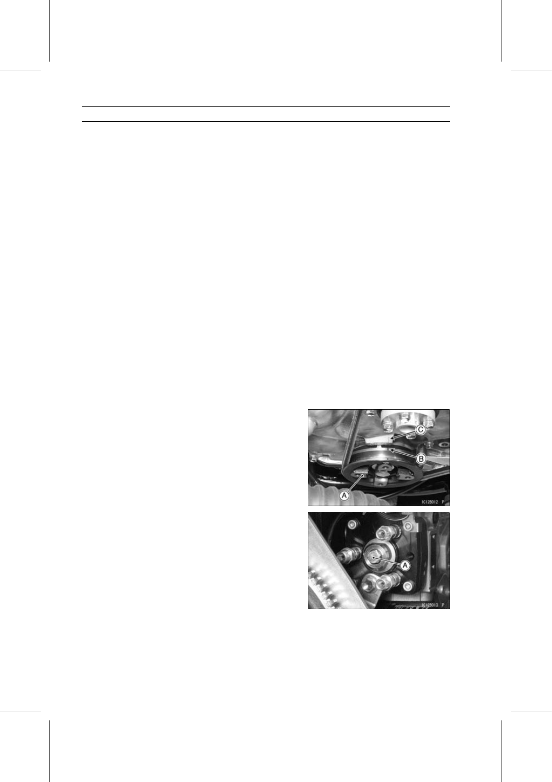
Turn the crankshaft pulley [A] clockwise, and position the
crankshaft at #1 piston TDC on the compression stroke.

Align the timing mark [B] on the crankshaft pulley and
reference point [C] on the timing case cover.

If the inlet and exhaust valves for #1 cylinder have no
clearance, turn the crankshaft pulley one revolution.

Remove the distributor bolt [A].

FUEL SYSTEM 3-19

Fuel Injection Pump

Install the dial gauge adapter [A] and dial gauge [B].

Special Tool - Dial Gauge Adapter: 57001-1430

Slowly turn the crankshaft pulley counterclockwise about
30° until the dial gauge needle stops. Pump plunger lift is
zero at this point.

Set the dial gauge to the “0” position.

Slowly turn the crankshaft pulley clockwise, stopping at
#1 piston TDC on the compression stroke.

NOTE

Do not turn the crankshaft pulley past TDC. If the crank-
shaft pulley is turned past TDC, turn the crankshaft back
to “0” on the dial gauge and repeat the procedure.

Note dial gauge reading.

Injection Timing (Plunger Stroke)

Marking of Injection Nozzle:

Red or Green:

0.81 ±0.03 mm (0.0319 ±0.0012 in.)

None:

0.81 ±0.02 mm (0.0319 ±0.0008 in.)

If the gauge reading is within the specification, the injec-
tion pump is properly timed.
If the gauge reading is not within the specification, adjust
the injection pump timing (see Fuel Injection Pump Timing
Adjustment).

Fuel Injection Pump Timing Adjustment

Inspect the fuel injection pump timing.

NOTE

Do not turn the crankshaft pulley past TDC. If the crank-
shaft pulley is turned past TDC, turn the crankshaft back
to “0” and repeat the procedure.

3-20 FUEL SYSTEM

Fuel Injection Pump

Loosen the fuel injection pump mounting nuts [A].

Loosen the fuel injection pump bracket bolt [A].

While observing the dial gauge, slowly rotate the fuel in-
jection pump away from the cylinder head until gauge
reads 0.81 ±0.03 mm (0.0319 ±0.0012 in.).

Hold the fuel injection pump in this position and tighten
the fuel injection pump mounting nuts.

NOTE

Do not rotate the pump past the specification. If the
pump is rotated past the specification, rotate the pump
back toward the cylinder head and repeat the proce-
dure.

Tighten:

Torque - Fuel Injection Pump Mounting Nuts: 20 N·m (2.0

kgf·m, 15 ft·lb)

Fuel Injection Pump Bracket Bolts: 20 N·m (2.0

kgf·m, 15 ft·lb)

To verify that the timing is correct, turn the crankshaft pul-
ley counterclockwise until the dial indicator reads “0”.

Then turn the crankshaft pulley clockwise until the timing
mark on the crankshaft pulley aligns with reference point
on the timing case cover.

The indicator should be within the specification.

Injection Timing (Plunger Stroke)

Marking of Injection Nozzle:

Red or Green:

0.81 ±0.03 mm (0.0319 ±0.0012 in.)

None:

0.81 ±0.02 mm (0.0319 ±0.0008 in.)

If the indicator reading is not within the specification, re-
peat the procedure.

Remove the dial gauge adapter and dial gauge.

Install the distributor head bolt and washer.

Tighten:

Torque - Distributor Head Bolt: 17 N·m (1.7 kgf·m, 13 ft·lb)

FUEL SYSTEM 3-21

Fuel Injection Pump

Fuel Injection Pump Inspection and Repair

NOTE

Do not disassemble the fuel injection pump and injec-
tion nozzles. The pump and nozzles are produced in
highly automated modern production facilities. They
cannot be assembled by hand in the field.

Refer to the troubleshooting section to check of the pump.
If the pump and nozzle are malfunction, replace them, or
consult a reliable repair shop (ex. Denso Service Station).


Content   ..  20  21  22  23   ..