Kawasaki Diesel MULE 4010 TRANS 4x4 (KAF950G9). Manual - part 20
 

  Index      Engines     Kawasaki Diesel MULE 4010 TRANS 4x4 (KAF950G9) - service manual


Search            


Content   ..  18  19  20  21   ..


Kawasaki Diesel MULE 4010 TRANS 4x4 (KAF950G9). Manual - part 20


3-10 FUEL SYSTEM

Throttle Pedal and Cable

Throttle Pedal Play Inspection

Refer to the Throttle Pedal Play Inspection in the Periodic
Maintenance chapter.

Throttle Pedal Play Adjustment

Refer to the Throttle Pedal Play Adjustment in the Periodic
Maintenance chapter.

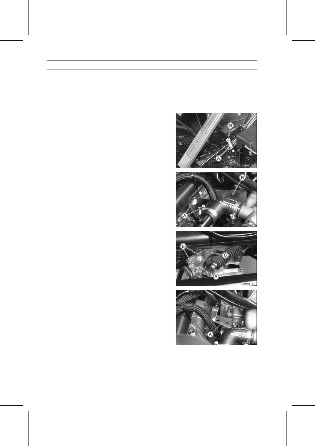
Full Throttle Pedal Position Adjustment

Loosen the locknut [A].

Screw in the throttle pedal stop bolt [B].

Tilt up the cargo bed.

Remove:

Injection Pump Cover Bolts [A] and Collars
Injection Pump Cover [B]

Reinstall the collars [A] and tighten the pump cover bolts
[B] together with the bracket [C] temporary.

Depress the throttle pedal until the speed control lever [A]
on the injection pump is in the fully opened position, and
hold it there.

Turn the throttle pedal stop bolt until the bolt head lightly
touches the bottom of the throttle pedal.

Tighten the locknut securely.

FUEL SYSTEM 3-11

Throttle Pedal and Cable

Throttle Cable Installation

Run the throttle cable correctly (see Cable, Wire, and
Hose Routing section in the Appendix chapter).

Adjust the throttle pedal play adjustment (see Throttle
Pedal Play Adjustment in the Periodic Maintenance chap-
ter).

WARNING

Operation with improperly adjusted, incorrectly
routed or damaged cables could result in an unsafe
riding condition. Follow the service manual to be
make sure to correct any of these conditions.

Throttle Cable Lubrication

Whenever the throttle cable is removed, lubricate the ca-

ble as follows.

Apply a thin coating of grease to the cable upper and
lower ends.

Lubricate the cable with a penetrating rust inhibitor
through a pressure cable luber.

Throttle Cable Inspection

With the throttle cable disconnected at both ends, the ca-
ble should move freely [A] within the cable housing.
If the cable does not move freely after lubricating, if the
cable is frayed [B], or if the housing is kinked [C], replace
the cable.

3-12 FUEL SYSTEM

Fuel Injection Nozzle

Fuel Injection Nozzle Removal

Tilt up the cargo bed.

Remove:

Fuel Injection Pipes (see Fuel Injection Pipe Removal)
Fuel Return Hose [A]
Linkage Pipe Nuts [B]
Linkage Pipe [C]

Remove:

Washer [A]
Fuel Injection Nozzle [B] and Gasket

NOTICE

Handle the fuel injection nozzles with extreme care.
Do not drop the nozzles.

Fuel Injection Nozzle Installation

Replace the gasket [A] with a new one.

Install the fuel injection nozzle [B].

Torque - Fuel Injection Nozzles: 59 N·m (6.0 kgf·m, 44 ft·lb)

Replace the washer [C] with a new one.

Install:

Linkage Pipe [D]
Linkage Pipe Nuts [E]

Torque - Linkage Pipe Nuts: 27 N·m (2.8 kgf·m, 20 ft·lb)

Install:

Fuel Return Hose
Fuel Injection Pipes (see Fuel Injection Pipe Installation)

Fuel Injection Nozzle Inspection

WARNING

Fuel is released from the injection nozzle at high
pressure and is highly flammable. Keep hands, fin-
gers and other body parts at least 12 inches from
the nozzle during testing. Do not smoke. Make sure
the area is well ventilated and free from any source
of flame or sparks; this includes any appliance with
a pilot light.

NOTE

Refer to the Fuel Injection Pump Inspection and Repair
for nozzle repair information.

FUEL SYSTEM 3-13

Fuel Injection Nozzle

Injection Pressure Check

Install the fuel injection nozzle on a nozzle tester.

Quickly move the tester lever up and down so that the
injection nozzle sprays two to three times.

This step blows off any carbon deposits on the injection
nozzle port.

Move the lever very slowly, gradually raising the pressure.

Measure the maximum pressure just as the pointer of the
pressure gauge drops suddenly.

Fuel Injection Nozzle Injection Pressure

Marking of Injection Nozzle:

Red or Green:

13 239

∼ 14 220 kPa (135 ∼ 145

kgf/cm², 1 920

∼ 2 062 psi)

None:

14 465

∼ 14 955 kPa (147.5 ∼ 152.5

kgf/cm², 2 098

∼ 2 169 psi)

If the measured pressure does not comply with the spec-
ification, replace the injection nozzle.

Leakage Check
(When there is a mark (green or red) on the nozzle.)

Slowly depress the tester lever, until the pressure reaches
about 11 768 kPa (120 kgf/cm², 1 706 psi.)

(When there is no mark on the nozzle.)

Slowly depress the tester lever, until the pressure reaches
about 12 749 kPa (130 kgf/cm², 1 849 psi.)

Checking for “Buzzing” and Spray Pattern

Operate the tester lever at a rate of 30 to 60 strokes per
minute in the case of a new nozzle; 15 to 60 strokes per
minute in the case of a used nozzle.

Make sure that “buzzing” occurs during these strokes.

NOTE

When this “buzzing” occurs, you can feel a pulsation
transmitted to your hand through the nozzle tester han-
dle while the nozzle injection is taking place.

When the pressurized fuel from the injection pump is in-
jected, this injection is accompanied by rapid, recurring
pressure variations during the time from the start to the
finish of the injection. These pulsing pressure variations
are felt as “buzzing”.

These pulsations of the fuel are affected mainly by the
movement of the nozzle needle and good or bad condi-
tions of the valve seat section.

Generally, a nozzle that “buzzes” is good, because a
spray condition where intermittent pulsations are gen-
erated assures good “cut-off” of the fuel supply.


Content   ..  18  19  20  21   ..