Kawasaki Diesel MULE 4010 TRANS 4x4 (KAF950G9). Manual - part 15
 

  Index      Engines     Kawasaki Diesel MULE 4010 TRANS 4x4 (KAF950G9) - service manual


Search            


Content   ..  13  14  15  16   ..


Kawasaki Diesel MULE 4010 TRANS 4x4 (KAF950G9). Manual - part 15


2-38 PERIODIC MAINTENANCE

Periodic Maintenance Procedures

Brake Wheel Cylinder Assembly Replacement

(Front Brake Panel)

Remove the brake drum (see Brake Drum Removal in the
Brakes chapter).

The left front brake panel is shown.

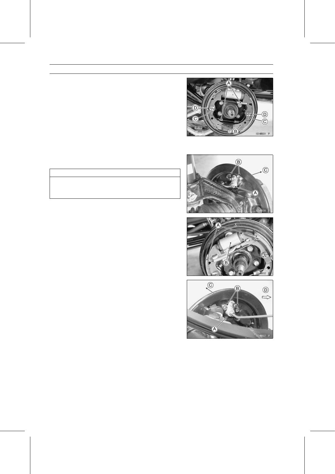
Remove the brake shoe springs [A] and brake shoes [B]
individually.

Push the shoe hold-down springs [C] and twist the pins
[D] to remove the shoes.

NOTE

Wrap the brake shoes with a clean cloth to protect the
linings from grease or dirt.

Remove the brake pipe nipple [A] and plug the nipple.

Immediately wipe up any brake fluid that spills.

NOTICE

Brake fluid quickly ruins painted surfaces; any
spilled fluid should be completely wiped up imme-
diately.

Unscrew the mounting bolts [B] and take off [C] the front
brake wheel cylinder.

(Rear Brake Panel)

Remove the brake shoes [A] in the same way as in the
front brake panel.

Rear Brake Wheel Cylinder [B]

(Rear Brake Panel)

Remove the brake pipe nipple [A] and plug the nipple.

Unscrew the mounting nuts [B] and take off [C] the rear
brake wheel cylinder.

Front [D]

PERIODIC MAINTENANCE 2-39

Periodic Maintenance Procedures

Replace the rear wheel cylinder with a new one.

Set the brake shoe clearance adjuster so that the drum
can be reinstalled on the panel assembly.

(Front Brake Panel)

Turn [A] either end of the cylinder fully while holding the
other end [B]. Both ends are put into the cylinder.

(Rear Brake Panel)

Push the ratchet [A] forwards and in to reset the shoe
clearance adjuster from the protruding position to its orig-
inal position. The stop [B] sets the position.

Left Parking Brake Lever Linkage [A] of Rear Brake

Ratchet [B]
Protruding Position [C]
Shoe Clearance Adjuster [E]
Front [F]

Left Parking Brake Lever Linkage [A] of Rear Brake

Ratchet [B]
Original Position [D]
Shoe Clearance Adjuster [E]
Front [F]

Apply brake fluid to the threads of the brake pipe nipple
and tighten it.

Torque - Brake Pipe Nipples: 18 N·m (1.8 kgf·m, 13 ft·lb)

Front Wheel Cylinder Mounting Bolts: 10.3 N·m

(1.1 kgf·m, 91 in·lb)

Rear Wheel Cylinder Mounting Nuts: 7.4 N·m (0.75

kgf·m, 65 in·lb)

2-40 PERIODIC MAINTENANCE

Periodic Maintenance Procedures

Apply grease to the following portions (front and rear
brake panels).

Brake Panel and Brake Shoe Contact Points [A]
Wheel Cylinder Piston Ends [B]
Brake Shoe Anchor Ends [C]

The left front brake is shown.

(Rear Brake Panel)

Grease the shoe clearance adjuster pivots [A].

(Rear Brake Panel)

Pack the gaps [A] with a little grease.

(Front and Rear Brake Panels)

Bleed the brake line after drum installation (see Brake
Line Air Bleeding in the Brakes chapter).

Be sure to check the brake system for good braking
power, no brake drag and no fluid leakage.

WARNING

After servicing, it takes several applications of the
brake pedal before the brake shoes contact the
drum, which could result in increased stopping
distance and cause an accident resulting in injury
or death. Do not attempt to ride the vehicle until a
firm brake pedal is obtained by pumping the pedal
until the shoes are against the drum.

Inspect the parking brake lever (see Parking Brake Lever
Inspection).

Parking Brake Lever Inspection

Check parking brake lever travel [A] by feeling clicks.

Pull the parking brake lever [B] upward slowly all the way.
Count the number of notches (clicks) during lever travel.

The vehicle should not roll while parked.

Parking Brake Lever Travel

Standard: 8

∼ 12 notches (clicks) at 200 N (20 kgf, 44

lb)

Release the parking brake and return the lever to its rest
position.

PERIODIC MAINTENANCE 2-41

Periodic Maintenance Procedures

If the lever travel is not correct, adjust it.

Pull up the rubber boot [A].

Loosen the locknut [B] and turn the adjusting nut [C] to
obtain the correct amount of lever travel.

Tighten the locknut.

Check the parking brake for good braking power and
when released, no brake drag.

WARNING

Insufficient free play can cause brake heating and
drag, resulting in skidding and loss of control which
could cause an accident resulting in serious injury
or death. Be sure the brake free play is adjusted to
the specification.

NOTE

If the parking brake lever travel cannot be adjusted with
the adjusting nut at the lever, remove the cover [A] and
use the adjusters [B] behind the parking brake lever and
adjusters [C] near the rear wheels. Be sure to adjust
both the left and right cables evenly, and then securely
tighten the adjuster mounting nuts [D].


Content   ..  13  14  15  16   ..