Kawasaki Diesel MULE 4010 TRANS 4x4 (KAF950G9). Manual - part 14
 

  Index      Engines     Kawasaki Diesel MULE 4010 TRANS 4x4 (KAF950G9) - service manual


Search            


Content   ..  12  13  14  15   ..


Kawasaki Diesel MULE 4010 TRANS 4x4 (KAF950G9). Manual - part 14


2-34 PERIODIC MAINTENANCE

Periodic Maintenance Procedures

Fill the reservoir with new brake fluid.

Temporarily install the reservoir cap.

Change the brake fluid as follows.

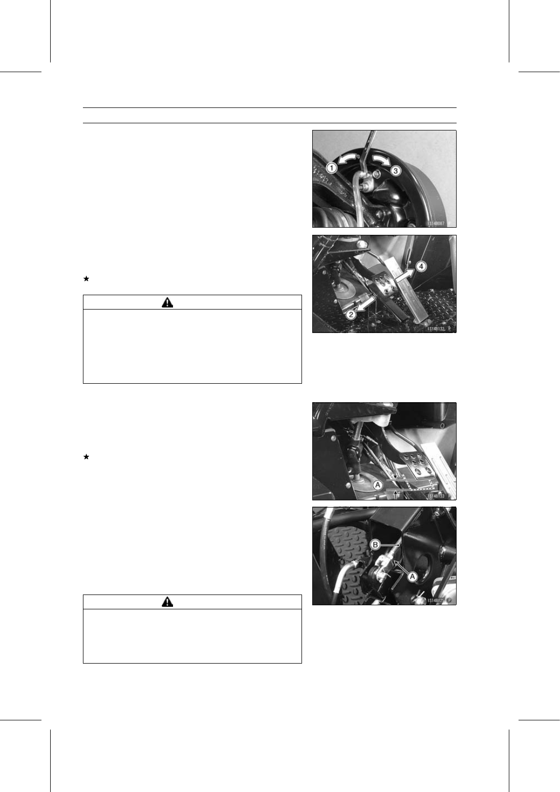
1. Open bleed valve.
2. Pump brake pedal and hold it.
3. Close bleed valve.
4. Release brake pedal.

Tighten:

Torque - Bleed Valves: 5.4 N·m (0.55 kgf·m, 48 in·lb)

Repeat the previous step for each wheel.

When brake fluid changing is finished, add the fluid to the
upper level in the reservoir.

After changing the fluid, check the brake for good braking
power, no brake drag, and no fluid leakage.
If necessary, bleed the air from the brake lines (see Brake
Line Air Bleeding in the Brakes chapter).

WARNING

Air in the brake lines diminish braking performance
and can cause an accident resulting in injury or
death. If the brake pedal has a soft or "spongy" feel-
ing mushy when it is applied, there might be air in
the brake lines or the brake may be defective. Do
not operate the vehicle and service the brake sys-
tem immediately.

Install the removed parts (see appropriate chapters).

Brake Pedal Play Inspection

Check the brake pedal play [A].

Brake Pedal Play

Standard: 2

∼ 10 mm (0.08 ∼ 0.39 in.)

If the play is not correct, adjust it.

Remove the front cargo compartment (see Front Cargo
Compartment Removal in the Frame chapter).

Loosen the locknut [A] and turn the push rod [B] to obtain
the correct amount of free play.

Tighten:

Torque - Push Rod Locknut: 17.2 N·m (1.8 kgf·m, 13 ft·lb)

Check the brake for good braking power and no brake
drag.

WARNING

Insufficient free play can cause brake heating and
drag, resulting in skidding and loss of control which
could cause an accident resulting in serious injury
or death. Be sure the brake free play is adjusted to
the specification.

PERIODIC MAINTENANCE 2-35

Periodic Maintenance Procedures

Brake Master Cylinder Cup and Dust Seal

Replacement

Remove the master cylinder (see Master Cylinder Re-
moval in the Brakes chapter).

Remove the piston stop bolt [G].

Remove the dust seal [A] and then the retainer [B] with
the circlip pliers.

Special Tool - Inside Circlip Pliers: 57001-143

Remove the piston assembly (two pistons) by lightly tap
the master cylinder on a wooden block.

Pistons [C]
Springs [D]
Secondary Cups [E]
Primary Cups [F]
Master Cylinder [H]

Be careful of the secondary cup direction [I].

Assemble the master cylinder.

Clean all the parts including the master cylinder with brake
fluid or alcohol, and apply brake fluid to the removed parts
and the inner wall of the cylinder.

NOTICE

Use only brake fluid, isopropyl alcohol, or ethyl al-
cohol for cleaning brake parts. Do not use any other
fluid for cleaning these parts. Gasoline, motor oil,
or any other petroleum distillate will cause deterio-
ration of the rubber parts. Oil spilled on any part will
be difficult to wash off completely, and will eventu-
ally deteriorate the rubber used in the brake.

Push the piston assembly in all the way with a screwdriver
and install the piston stop bolt. Use a new aluminum
washer.

Tighten:

Torque - Piston Stop Bolt: 8.8 N·m (0.90 kgf·m, 78 in·lb)

Reservoir Clamp Bolt: 6.1 N·m (0.62 kgf·m, 54

in·lb)

Install the master cylinder (see Master Cylinder Installa-
tion in the Brakes chapter).

Brake Hose and Pipe Inspection

The high pressure inside the brake line can cause fluid to
leak [A] or the hose to burst if the line is not properly main-
tained. Bend and twist the rubber hose while examining
it.
Replace it if any cracks [B] or bulges [C] are noticed.

The metal pipe will rust if the plating is damaged.
Replace the pipe if it is rusted, cracked (especially check
the fittings), or if the plating is badly scratched (see Brake
Hose and Pipe Replacement).

2-36 PERIODIC MAINTENANCE

Periodic Maintenance Procedures

Brake Hose and Pipe Replacement

To remove the brake pipe [A], unscrew the nipple [B].

To remove the hoses [C], remove the banjo bolts [D]
and/or pull out the retainers.

The front cargo compartment inside is shown.

Immediately wipe up any brake fluid that spills.

NOTICE

Brake fluid quickly ruins painted surfaces; any
spilled fluid should be completely wiped up imme-
diately.

Use a new copper washer for each side of the hose fittings
at the master cylinder.

Apply brake fluid to the threads of the nipple [B] of the
brake pipe [A].

Tighten:

Torque - Brake Hose Banjo Bolts: 25 N·m (2.5 kgf·m, 18

ft·lb)

Brake Pipe Nipples: 18 N·m (1.8 kgf·m, 13 ft·lb)

Check that the brake line has proper fluid pressure and
no fluid leakage.

The left front brake drum is shown.

The left front knuckle is shown.

Brake Pipe [A]
Nipple [B]
Brake Hose [C]
Retainer [D]

The rear-middle of the vehicle is shown with the cargo
bed tilted up.

Brake Hose and Pipes [A]
Nipples [B]

PERIODIC MAINTENANCE 2-37

Periodic Maintenance Procedures

The middle-left of the vehicle is shown with the cargo bed
tilted up.

Brake Pipe [A]
Nipple [B]
Brake Hose [C]
Retainer [D]
Torque Converter Outer Cover [E]
Front [F]

The rear-left brake line is shown.

Brake Pipe [A]
Nipple [B]
Brake Hose [C]
Retainer [D]
Front [E]

Brake Wear Inspection

Remove the brake drum (see Brake Drum Removal in the
Brakes chapter).

Measure the inside diameter [A] of the drum at several
points.
If any measurement is greater than the service limit, re-
place the drum.
If the drum is worn unevenly or scored, lightly turn the
drum on a brake drum lathe or replace it. Do not turn the
drum beyond the service limit.

Brake Drum Inside Diameter

Standard:

180.000

∼ 180.160 mm

(7.0866

∼ 7.0929 in.)

Service Limit: 180.75 mm (7.116 in.)

Remove the brake drum for brake shoe inspection (see
Brake Drum Removal in the Brakes chapter).

Measure the lining thickness at several points.

Brake Shoe Lining Thickness

Standard:

4.5 mm (0.18 in.)

Service Limit: 1.0 mm (0.04 in.)

If any measurement is less than the service limit, replace
both shoes as a set.
If the lining thickness is greater than the service limit, do
the following before installing the shoes.

File or sand down any high spots on the surface on the
lining.

Use a wire brush to remove any foreign particles from the
lining.

Wash off any oil or grease with an oilless solvent.

NOTICE

Do not use a solvent which will leave an oily
residue. The shoes will have to be replaced.


Content   ..  12  13  14  15   ..