Kawasaki Diesel MULE 4010 TRANS 4x4 (KAF950G9). Manual - part 13
 

  Index      Engines     Kawasaki Diesel MULE 4010 TRANS 4x4 (KAF950G9) - service manual


Search            


Content   ..  11  12  13  14   ..


Kawasaki Diesel MULE 4010 TRANS 4x4 (KAF950G9). Manual - part 13


2-30 PERIODIC MAINTENANCE

Periodic Maintenance Procedures

Oil Filter Removal

Tilt up the cargo bed.

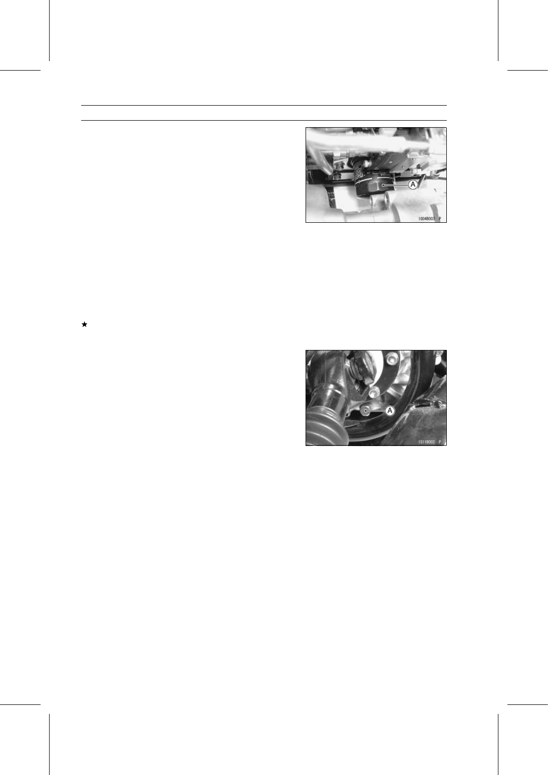
Remove the oil filter [A] from under the vehicle.

When unscrewing the oil filter, cover the filter bottom with
a clean cloth so as not to spill the engine oil out of the
filter. Any spilled oil should be wiped up completely.

Oil Filter Installation

Apply engine oil to the oil filter gasket.

Install a new filter.

Screw the filter in until the gasket touches the engine, then
turn it 1 turn.

Add the engine oil (see Engine Oil and/or Oil Filter
Change).

Thoroughly warm up the engine, and check for oil leakage
and the oil level.
If necessary, add more engine oil.

Transmission

Transmission Oil Change

Warm up the oil by running the vehicle so that the oil will
pick up any sediment and drain easily. Then stop the
vehicle.

Place an oil pan beneath the transmission case.

Remove the transmission oil drain plug [A], and let the oil
drain completely.

Replace the gasket with a new one.

After the oil has completely drained out, install the drain
plug with the gasket.

Torque - Transmission Oil Drain Plug: 15 N·m (1.5 kgf·m,

11 ft·lb)

Fill the transmission case with a good quality oil as spec-
ified in the table.

Check the oil level.

Transmission Oil

Type:

Hypoid gear oil

Viscosity: SAE 90: above 5°C (41°F) or

SAE 80: below 5°C (41°F)

Capacity:

2.5 L (2.6 US qt)

Oil Level:

Between H and L level lines on dipstick

PERIODIC MAINTENANCE 2-31

Periodic Maintenance Procedures

Wheels/Tires

Wheels Nuts Tightness Inspection

Check the tightness of all the wheel nuts.
If there are loose nut, first loosen by 1/2 turn, then re-
torque them to the specified torque.

Torque - Wheel Nuts: 137 N·m (14.0 kgf·m, 101 ft·lb)

Tighten the wheel nuts [1]

∼ [4] in a criss-cross pattern.

Tire Wear Inspection

Examine the tire for damage and wear.
If the tire is cut or cracked, replace it.

Lumps or high spots on the tread or sidewalls indicate
internal damage, requiring tire replacement.

Remove any foreign objects from the tread. After re-
moval, check for leaks with a soap and water solution.

Measure the tread depth at the center of the tread with a
depth gauge [A]. Since the tire may wear unevenly, take
measurements at several places.
If any of the measurements is less than the service limit,
replace the tire.

Tire Tread Depth

Standard:

13.2 mm (0.52 in.)

Service Limit 3 mm (0.12 in.)

Standard Tire

Front and Rear: 23 × 11.00-10 DUNLOP KT869 Tubeless

Final Drive

Front Final Gear Case Oil Change

Warm up the oil by running the vehicle so that the oil will
pick up any sediment and drain easily. Then stop the
vehicle.

Park the vehicle so that it is level, both side-to-side and
front-to-rear.

Remove the front final gear case skid plate (see Front
Final Gear Case Oil Level Inspection in the Final Drive
chapter).

Place an oil pan beneath the front final gear case and
remove the drain plug [A].

WARNING

Oil on tires can cause loss of traction and an ac-
cident resulting in serious injury or death. When
draining or filling the final gear case, do not spill oil
the tire or rim. Clean any oil that may spill with a
high flash-point solvent.

2-32 PERIODIC MAINTENANCE

Periodic Maintenance Procedures

After the oil has completely drained out, install the drain
plug with a new aluminum gasket, and tighten it.

Torque - Oil Drain Plug: 20 N·m (2.0 kgf·m, 15 ft·lb)

Fill the gear case up to the bottom [A] of filler opening [B]
with the oil specified below.

Front Final Gear Case Oil

Type:

Hypoid gear oil for LSD (Limited Slip
Differential gears)

Viscosity: SAE 140 (GL-5) or SAE 90 (GL-6)
Capacity:

0.4 L (0.4 US qt)

Oil Level:

Filler opening level

NOTE

“GL-5 or GL-6” indicate a quality and additive rating.

Be sure the O-ring [A] is in place, and tighten the filler cap.

Filler Opening [B]

Torque - Oil Filler Cap: 29 N·m (3.0 kgf·m, 21 ft·lb)

Install the front final gear case skid plate (see Front Final
Gear Case Oil Level Inspection in the Final Drive chapter).

Brakes

Brake Fluid Level Inspection

With the vehicle on level ground, check that the fluid level
in the reservoir is between the upper (MAX) and lower
(MIN) level lines.

Look the fluid level through the hole [A] in the control
panel.
If the fluid level is lower than the lower level line, check
for fluid leaks in the brake lines, and fill the reservoir to
the upper level line.

WARNING

Mixing brands and types of brake fluid can reduce
the brake system’s effectiveness and cause an ac-
cident resulting in injury or death. Do not mix two
brands of brake fluid. Change the brake fluid in the
brake line completely if the brake fluid must be re-
filled but the type and brand of the brake fluid that
is already in the reservoir are unidentified.

Tilt up the front cargo hood.

Remove:

Rubber Cap [A]

PERIODIC MAINTENANCE 2-33

Periodic Maintenance Procedures

Fill the reservoir to the upper level line [A].

Upper Level Line (MAX)
Lower Level Line (MIN) [B]
Hole [C] of Front Cargo Compartment

Apply the brake forcefully for a few seconds and check for
fluid leakage around the fittings.

WARNING

Air in the brake lines diminish braking performance
and can cause an accident resulting in injury or
death. If the brake pedal has a soft or "spongy" feel-
ing mushy when it is applied, there might be air in
the brake lines or the brake may be defective. Do
not operate the vehicle and service the brake sys-
tem immediately.

Brake Fluid Change

Tilt up the front cargo hood.

Level the brake fluid reservoir [A].

NOTE

The fluid level must be checked several times during
the fluid changing and replenished as necessary. If the
fluid in the reservoir runs completely out any time during
fluid changing, air bleeding must be done since air will
have entered the line.

Remove the wheel for extra clearance (see Wheel Re-
moval in the Wheels/Tires chapter).

Remove the reservoir cap.

Remove the rubber cap from the bleed valve on the wheel
cylinder.

Connect a clear plastic hose [A] to the bleed valve at the
wheel cylinder, running the other end of the hose into a
container.

Left Front Brake Panel [B]

NOTE

Start with the rear left or right wheel and finish with the
front left or right wheel.


Content   ..  11  12  13  14   ..