Kawasaki Diesel MULE 4010 TRANS 4x4 (KAF950G9). Manual - part 11
 

  Index      Engines     Kawasaki Diesel MULE 4010 TRANS 4x4 (KAF950G9) - service manual


Search            


Content   ..  9  10  11  12   ..


Kawasaki Diesel MULE 4010 TRANS 4x4 (KAF950G9). Manual - part 11


2-22 PERIODIC MAINTENANCE

Periodic Maintenance Procedures

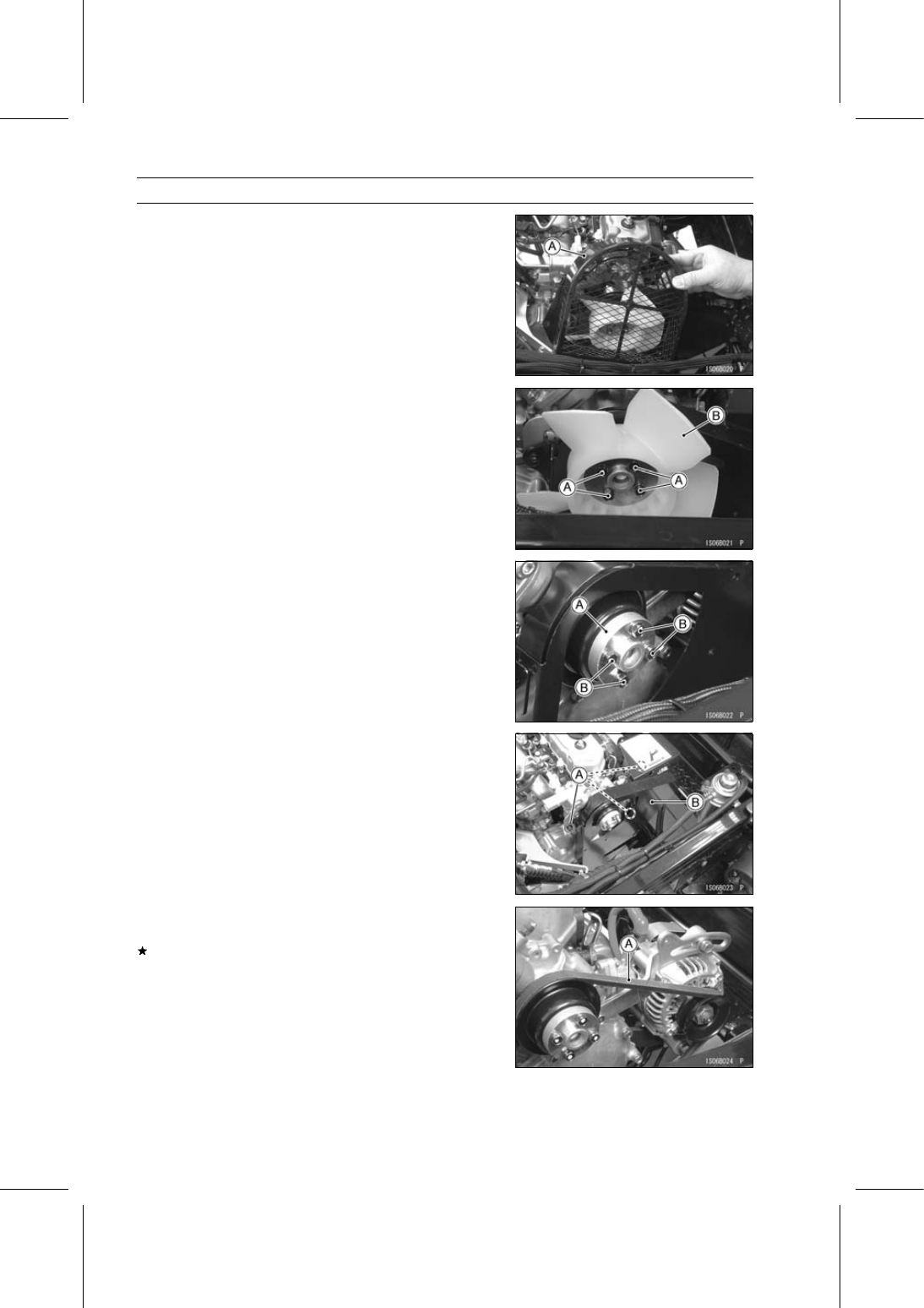
Remove the fan cover [A] as shown in the figure.

Remove:

Fan Mounting Bolts [A]
Cooling Fan [B]
Spacer

Reinstall the spacer [A] and tighten the fan mounting bolts
[B] temporary.

Torque - Fan Mounting Bolts: 8.8 N·m (0.90 kgf·m, 78 in·lb)

Remove:

Bolts [A]
Fan Belt Cover [B]

Check the cooling fan belt [A] for excessive wear crack or
broken.
If necessary, replace the belt with a new one.

PERIODIC MAINTENANCE 2-23

Periodic Maintenance Procedures

Check the fan belt deflection.

Use a ruler [A], push the belt with 98 N (10 kgf, 22 lb)
force.

Push Gauge [B]

Fan Belt Deflection

Standard: 9.5

∼ 11.5 mm (0.37 ∼ 0.45 in.)

If the deflection is incorrect, adjust it.

Loosen the alternator adjusting bracket bolt [A] and alter-
nator mounting bolt [B].

Alternator [C]

Adjust the fan belt deflection.

Use a ruler, push the belt with 98 N (10 kgf, 22 lb) force.

Tighten the bolts.

Torque - Alternator Adjusting Bracket Bolts: 20 N·m (2.0

kgf·m, 15 ft·lb)

Alternator Mounting Bolt: 39 N·m (4.0 kgf·m, 29

ft·lb)

When installing the water pipe and water hose, note the
following.

Check that the damper [A] is in place on the water pipe
[B].

Air Bleed Bolt [C]
5

∼ 10 mm (0.20 ∼ 0.40 in.) [D]

If the damper is damaged or deteriorated, replace it.

Insert the water pipe [A] up to the end of the bending
radius of the water hose [B] as shown in the figure.

Air Bleed Bolt [C]

Make sure that there is clearance between the water pipe
and the fan cover.

Engine Top End

Valve Clearance Inspection

NOTE

Valve clearance must be checked when the engine is
cold (at room temperature).

Remove:

Fan Belt Cover (see Cooling Fan Belt Inspection)
Cylinder Head Cover (see Rocker Arm Components Re-
moval in the Engine Top End chapter)

2-24 PERIODIC MAINTENANCE

Periodic Maintenance Procedures

Turn the crankshaft pulley [A] clockwise so that the timing
mark [B] on the pulley aligns with the reference point [C]
on the timing gear case cover.

Check that the rocker arms at #1 cylinder are free.
If not, turn the pulley one more turn to free the rocker
arms.

Using a thickness gauge [A], measure the valve clearance
between the rocker arm [B] and the valve stem cap [C].
If the valve clearance is incorrect, adjust it.

Valve Clearance

Standard: 0.20 mm (0.0079 in.)

When positioning #1 piston TDC at the compression
stroke:

Inlet valve clearance of #1 and #3 cylinders
Exhaust valve clearance of #1 and #2 cylinders
Front [A]
Measuring Valve [B]

Turn the crankshaft pulley 360° clockwise.

Inlet valve clearance of #2 cylinder
Exhaust valve clearance of #3 cylinder
Front [A]
Measuring Valve [B]

Valve Clearance Adjustment

Loosen the valve adjusting screw locknut [A].

Turn the valve adjusting screw [B] until the correct clear-
ance is obtained.

Holding the adjusting screw, tighten the locknut.

Torque - Valve Adjusting Screw Locknuts: 11 N·m (1.1

kgf·m, 97 in·lb)

PERIODIC MAINTENANCE 2-25

Periodic Maintenance Procedures

Spark Arrester Cleaning

WARNING

The muffler can become extremely hot during nor-
mal operation and cause severe burns. Since the
engine must be running during this procedure, wear
heat-resistant gloves while cleaning the spark ar-
rester.

Remove the drain plug [A] from the muffler [B].

Apply the parking brake.

In an open area away from combustible materials, start
the engine with the gear shift lever in the N (neutral) po-
sition.

Raise and lower engine speed while tapping on the muf-
fler with a rubber mallet until the carbon particles are
purged from the muffler.

DANGER

Exhaust gas contains carbon monoxide, a color-
less, odorless poisonous gas.

Inhaling carbon

monoxide can cause serious brain injury or death.
DO NOT run the engine in enclosed areas. Operate
only in a well-ventilated area.

Stop the engine.

Install the drain plug.

Converter System

Drive Belt Inspection

Remove the drive belt (see Drive Belt Removal in the
Converter System chapter).

Measure the width [A] of the belt.
If any measurements exceed the service limit, replace the
belt.

Belt Width

Standard:

34.1 mm (1.34 in.)

Service Limit: 32.6 mm (1.28 in.)

Check the belt for wear, cracks, breaks or peeling.
If necessary, replace the belt with a new one.

Belt [A]
Crack [B]
Broken [C]

NOTE

Whenever the belt is replaced, inspect the drive and the
driven pulleys.


Content   ..  9  10  11  12   ..