Kawasaki Diesel MULE 4010 TRANS 4x4 (KAF950G9). Manual - part 9
 

  Index      Engines     Kawasaki Diesel MULE 4010 TRANS 4x4 (KAF950G9) - service manual


Search            


Content   ..  7  8  9  10   ..


Kawasaki Diesel MULE 4010 TRANS 4x4 (KAF950G9). Manual - part 9


2-14 PERIODIC MAINTENANCE

Periodic Maintenance Procedures

Fuel System

Throttle Pedal Play Inspection

Check that the throttle pedal moves smoothly from full
open to close.
If the throttle pedal does not return properly, lubricate the
throttle cable and link (see Throttle Cable Lubrication in
the Fuel System chapter).

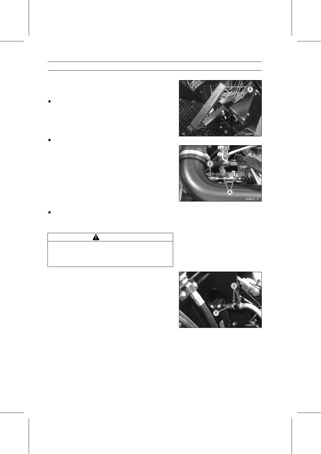
Check the throttle pedal play [A].

Throttle Pedal Play

Standard:

5

∼ 10 mm (0.20 ∼ 0.39 in.)

If the play is incorrect, adjust the throttle cable.

Throttle Pedal Play Adjustment

Tilt up the cargo bed.

Loosen the adjuster mounting nuts [A] at the engine end
of the cable.

Slide the adjuster [B] until the proper amount of throttle
pedal play is obtained.

Tighten the adjuster mounting nuts securely.

Start the engine.

With the transmission in neutral, operate the throttle pedal
a few times to make sure that the idle speed does not
change.
If the idle speed does change, the throttle cable may be
improperly adjusted, incorrectly routed, or it may be dam-
aged.

Correct any of these conditions before operation.

WARNING

Operation with improperly adjusted, incorrectly
routed or damaged cables could result in an unsafe
riding condition. Follow the service manual to be
make sure to correct any of these conditions.

NOTE

If the throttle pedal play can not be adjusted by using
the adjuster at the engine end of the cable, use the ca-
ble adjuster [A] at the throttle pedal. Do not forget to
securely tighten the adjuster mounting nuts [B].

PERIODIC MAINTENANCE 2-15

Periodic Maintenance Procedures

Idle Speed Inspection

Start the engine and warm it up thoroughly.

Tilt up the cargo bed.

Check the idle speed with a suitable tachometer [A].

Tachometer Adapter [B]

Idle Speed

Standard: 850

∼ 950 r/min (rpm)

If the idle speed is out of the specified range, adjust it.

Idle Speed Adjustment

Start the engine and warm it up thoroughly.

Loosen the locknut [A].

Turn the idle adjusting screw [B] at the injection pump until
the idle speed is correct.

Tighten:

Torque - Idle Adjusting Screw Locknut: 6.9 N·m (0.70

kgf·m, 61 in·lb)

Open and close the throttle a few times to make sure that
the idle speed is within the specified range. Readjust if
necessary.

Fuel Hoses and Connections Inspection

Tilt up the cargo bed and seat.

Check the fuel hoses and fittings for deterioration, cracks
and signs of leakage.
Replace the fuel hose if any fraying, leak [A], cracks [B]
or bulges [C] are noticed.

Check that the hoses are securely connected and clamps
are installed correctly.

When installing, run the hoses according to Cable, Wire,
and Hose Routing section in the Appendix chapter.

When installing the fuel hoses, avoid sharp bending, kink-
ing, flattening or twisting, and route the fuel hoses with a
minimum of bending so that the fuel flow will not be ob-
structed.
Replace the hose if it has been sharply bent or kinked.

Fuel Hoses Replacement

Tilt up the cargo bed and seat.

Remove:

Front Seat Lower Cover Front (see Floor Center Panel
Removal in the Frame chapter)
Clamps [A]
Fuel Hoses [B]

2-16 PERIODIC MAINTENANCE

Periodic Maintenance Procedures

Remove:

Clamps [A]
Fuel Hoses [B]

Remove:

Clamps [A]
Fuel Hoses [B]

Remove:

Clamp [A]
Fuel Hose [B]
Fuel Filter Mounting Bolts [C]

Remove:

Clamps [A]
Fuel Hoses [B]

When installing, run the hoses according to Cable, Wire,
and Hose Routing section in the Appendix chapter.

When installing the fuel hoses, avoid sharp bending, kink-
ing, flattening or twisting, and run the fuel hoses with a
minimum of bending so that the fuel flow will not be ob-
structed.

PERIODIC MAINTENANCE 2-17

Periodic Maintenance Procedures

Fit the fuel hose [A] onto the fitting fully and install the
plate clamp [B] beyond the raised rib [C].

1

∼ 2 mm (0.039 ∼ 0.079 in.) [D]

The hose end must reach the filler [E] or be as near as
possible to the step [F].

Bleed the air from the fuel filter (see Fuel Filter Installation
in the Fuel System chapter).

Fuel Filter Element Replacement

Remove:

Fuel Filter (see Fuel Filter Removal in the Fuel System
chapter)
Drain Cap [A]
O-ring [B]
Filter Cartridge [C]

Use a suitable filter wrench.

Install a new filter cartridge by hand until the gasket con-
tacts the housing. Then tighten it 1/3 turn more.

Install:

Drain Cap
New O-ring
Fuel Filter (see Fuel Filter Installation in the Fuel System
chapter)

Fuel Filter Water Draining

Tilt up the cargo bed.

Place a suitable container under the filter drain hose [A].

Loosen the air vent plug [B].

Loosen the drain cap [C] approximately 1 turn, and drain
water from the filter until only fuel flows from the filter.

Tighten the drain cap securely.

Bleed the air from the fuel filter (see Fuel Filter Element
Replacement).

Wipe off any spilled fuel.

Start the engine, and check for fuel leakage.


Content   ..  7  8  9  10   ..