AIRTRONIC / AIRTRONIC M. Manual - part 6
 

  Index      Engines     Eberspacher AIRTRONIC / AIRTRONIC M - service manual


Search            


Content   ..  4  5  6  7   ..


AIRTRONIC / AIRTRONIC M. Manual - part 6


21

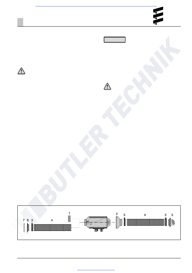
Heater air system (example)

Heater air system

The parts for the hot air system are included in the
scope of supply of the "Universal" and "Plus"
installation kits.
The "Plus" installation kit does not include the flexible
pipe Ø 75 mm or Ø 90 mm, these must be ordered
separately. The order no. is given in the additional
parts catalogue.

Danger!

Risk of burning and injuries!
• The hoses of the heater air system and the hot air

outlet are to be routed and fastened in such a way
that they pose no temperature risk to people,
animals or materials sensitive to temperature from
radiation / contact or blowing directly. If necessary,
a cover is to be fitted to the heater air system or
hot air outlet.

• The outflow hood must be fitted on the hot air

outflow side.

• A safety grid must be fitted to the heater air intake

side and outflow side if no air hoses are mounted,
to prevent any injuries from the heater air fan or
burns from the heat exchanger.

• High temperatures occur in the heater air system

during and after the heater has been working.
This is why it is important to avoid working in the
vicinity of the heater air system while the heater is
working. In such cases, switch the heater off
beforehand and wait until all parts have cooled
down completely.
If necessary, wear safety gloves.

Caution!

• The heater air intake openings must be arranged in

such a way that under normal circumstances, it is
not possible for exhaust from the vehicle engine and
heater to be sucked into the system, or for the
heating air to be contaminated with dust, salt spray,
etc.

• For circulating air, position the circulating air intake

in such a way that the outflowing hot air cannot be
directly sucked in again.

• In the event of possible overheating, it is possible

for local lot air temperatures of up to max. 150 °C
or surface temperatures of up to max. 90 °C to
occur immediately before the defect shutdown.
Therefore only temperature-resistant hot air hoses
approved by us must be used for the heater air
system!

• When checking the functions, the mean outflow

temperature measured after the heater has been
running about 10 minutes at approx. 30 cm from the
outlet should not exceed 110 °C (at an intake
temperature of approx. 20 °C).

• If there is a risk of the driver and passengers

touching the heater when the vehicle is being driven
normally, a contact protection device must be fitted.

Installation

3

1

Safety grid

2

Outflow hood

3

Hose clip

4

Flexible hose

5

Rotating outflow

6

Connection fitting

7

Safety grid

Please note!

• Installation of spherical reduction hood is not

permitted in the Airtronic D4 Plus.

• The regulations and safety instructions to be observed

for this chapter are on page 4 – 7.

• If air duct parts are connected the heater code

number in “Using Universal Installation Kits”, page 8
and “Using Plus Installation Kits”, page 10 must be
observed.

22

Installation

3

Exhaust system

Mounting the exhaust system

The “Universal” and “Plus” installation kits include a
flexible exhaust pipe, inner Ø 24 mm, 1000 mm long
and an exhaust silencer. The flexible exhaust pipe can
be shortened to 20 cm or lengthened to max. 2 m,
depending on the installation conditions.
Fasten the exhaust silencer to a suitable position in
the vehicle.
Route the flexible exhaust pipe from the heater to the
exhaust silencer and fasten with pipe clips. Use a
pipe clip to fix a short exhaust pipe end (with end
sleeve) to the exhaust silencer.

Caution!

Safety instructions!
The whole exhaust system gets very hot during and
immediately after the heater has been working. This is
the reason why the exhaust system must be installed
according to these instructions.
• The exhaust outlet must end in the open air.
• The exhaust pipe must not protrude beyond the

lateral limits of the vehicle.

• Install the exhaust pipe sloping slightly downwards.

If necessary, make a drain hole approx. Ø 5 mm at
the lowest point to drain off condensation.

• Important functional parts of the vehicle must not be

impaired (keep sufficient clearance).

• Mount the exhaust pipe with sufficient clearance to

heat-sensitive parts. Pay particular attention to fuel
pipes (plastic or metal), electrical cables and brake
hoses etc.!

• Exhaust pipes must be fastened safely

(recommended clearance of 50 cm) to avoid damage
from vibrations.

• Route the exhaust system so that the emitted fumes

are not sucked in with the combustion air.

• The mouth of the exhaust pipe must not get clogged

by dirt and snow.

• The mouth of the exhaust pipe must not point in the

direction of travel.

• Always fasten the exhaust silencer to the vehicle.

Danger!

Risk of injuries and burns!
Every type of combustion produces high temperatures
and toxic exhaust fumes. This is the reason why the
exhaust system must be installed according to these
instructions.
• Do not perform any work on the exhaust system

while the heater is working.

• Before working on the exhaust system, first switch

the heater off and wait until all parts have cooled
down completely, wear safety gloves if necessary.

• Do not inhale exhaust fumes.

• Comply with the regulations and safety instructions

for this chapter on page 4 – 7.

• If a silencer is fitted, the exhaust end pipe must be

much shorter than the flexible exhaust pipe
between the heater and the exhaust silencer.

• Small arrows indicating the direction of flow have

been cast into the fittings to differentiate between
the combustion air and the exhaust fittings at the
heater (see diagram page 23).

Please note!

23

Caution!

Safety instructions for the combustion
air system!
• The combustion air opening must be free at all

times.

• Position the combustion air intake to be sure that

exhaust fumes cannot be sucked in with the
combustion air.

• Do not arrange the combustion air intake to pointing

against the wind blast.

• The combustion air intake must not get clogged with

dirt and snow.

• Install the combustion air intake system sloping

slightly downwards. If necessary, make a drain hole
approx. Ø 5 mm at the lowest point to drain off
condensation.

Combustion air system

Mounting the combustion air system

The universal installation kit includes a flexible
combustion air hose, inner Ø 25 mm , 1000 mm long.
If necessary the flexible combustion air hose can be
shortened to 20 cm or lengthened to max. 2 m
depending on the installation conditions.
Fasten the combustion air hose to the heater with
a pipe clip and at suitable points with hose clips or
cable ties.
Fit an end sleeve after completing the installation.

The „Plus“ installation kit includes a combustion air
intake silencer with a flexible connection hose (inner
diameter 25 mm).
Fasten the flexible connection hose to the heater with
a pipe clip and fasten the combustion air intake
silencer with hose clips or cable ties at suitable points.
Fit an end sleeve after completing the installation.

1

Combustion air hose, di = 25 mm

2

Combustion air silencer,
– Included in the “Plus” installation kit

3

Exhaust pipe, di = 24 mm

4

Exhaust silencer

5

Intake / outlet opening – protect from wind,
snow, dirt and water.

6

End sleeve, combustion air

7

End sleeve, exhaust

8

Combustion air connection

9

Exhaust connection

10 End sleeve, combustion air
11 Hose clip
12 Exhaust hose clip

Installation

3

Please note!

• For Airtronic and Airtronic M heaters a combustion

air intake silencer can be fitted instead of the com-
bustion air hose to reduce the noise level. The order
number is stated in the Accessories Catalogue.

• Comply with the regulations and safety instructions

for this chapter on page 4 – 7.

max. 2 m

min. 0.2 m

min. 0.2 – max. 2 m

24

Installation

3

1

Correct connection

2

Incorrect connection – bubble formation

Fuel supply

Mounting the dosing pump, routing the fuel pipes
and mounting the fuel tank

The following safety instructions must be observed
when mounting the dosing pump, routing the fuel pipes
and mounting the fuel tank.
Deviations from the instructions stated here are not
allowed.
Failure to comply can result in malfunctions.

Danger!

Risk of fire, explosion, poisoning and injuries!

Caution when handling fuel.

• Switch off the vehicle engine and heater before

refuelling and before working on the fuel supply.

• No naked lights when handling fuel.

• Do not smoke.

• Do not inhale fuel vapours.

• Avoid any contact with the skin.

Caution!

Safety instructions for routing the fuel pipes!

• Only use a sharp knife to cut off fuel hoses and

pipes.
Interfaces must not be crushed and must be free
of burrs.

• The fuel pipe from the dosing pump to the heater

should be routed at a continuous rise.

• Fuel pipes must be fastened safely to avoid any

damage and / or noise production from vibrations
(recommended clearance of approx. 50 cm).

• Fuel pipes must be protected from any mechanical

damage.

• Route the fuel pipes so that any distortion of the

vehicle, engine movements etc. cannot have any
lasting effect on the service life.

• Parts carrying fuel must be protected from

interfering heat.

• Never route or fasten the fuel pipes to the heater or

vehicle exhaust system. At crossings, always ensure
adequate heat clearance, if necessary attach heat
deflection plates or protective hose (for Order No.
protective hose please refer to additional parts
catalogue).

• Dripping or evaporating fuel must never be allowed

to collect on hot parts or ignite on electric systems.

• When connecting fuel pipes with a fuel hose, always

mount the fuel pipes in a butt joint to prevent any
bubbles from forming.

Safety instructions for fuel pipes and fuel tanks
in buses and coaches

• In buses and coaches, fuel pipes and fuel tanks

must not be routed through the passenger
compartment or driver’s cab.

• Fuel tanks in buses and coaches must be

positioned in such a way that the exits are not in
direct danger from a possible fire.

• Comply with the regulations and safety instructions

for this chapter on page 4 – 7.

• For noise reasons, do not rigidly fit fuel pipes onto

structural sound transferring components.
A sponge rubber hose can be pushed over the fuel
tubes for nose reduction.

Please note!


Content   ..  4  5  6  7   ..